

Environment-friendly long-acting electrolytic ion grounding electrode and construction method thereof
A technology of electrolytic ion and construction method, applied in the direction of connecting contact materials, etc., can solve the problem of unsuitable use of deep holes, etc., and achieve the effects of cheap performance, solving the problem of resistance reduction, and short radiation length.
- Summary
- Abstract
- Description
- Claims
- Application Information
AI Technical Summary
Problems solved by technology
Method used
Image

Examples
Embodiment 1
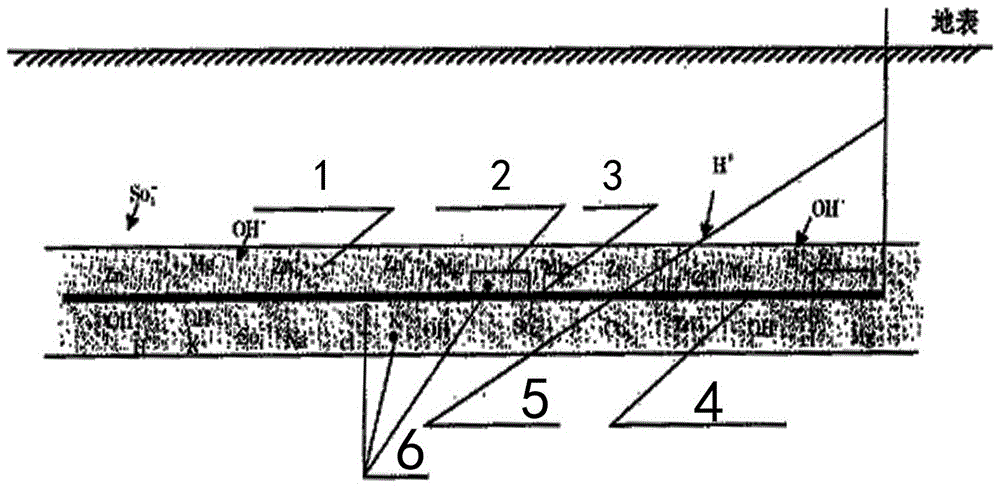
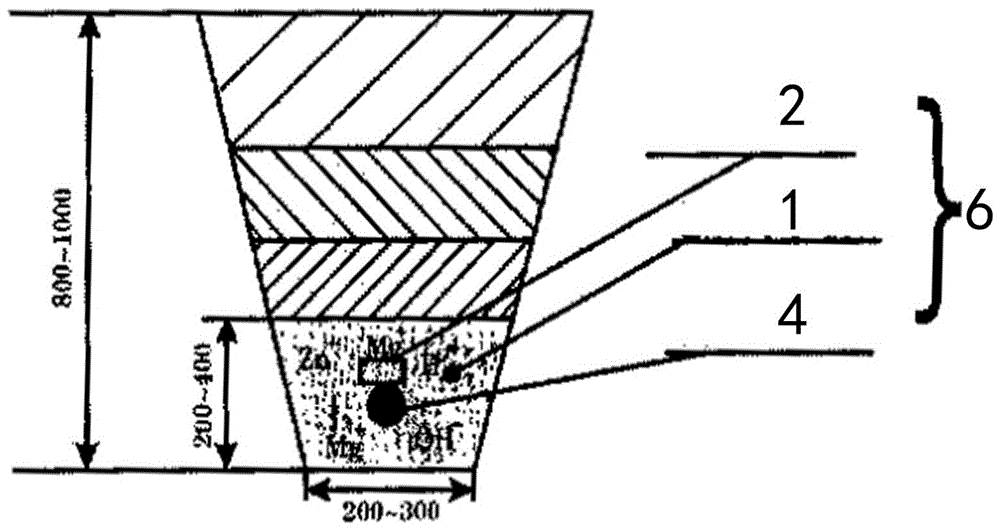
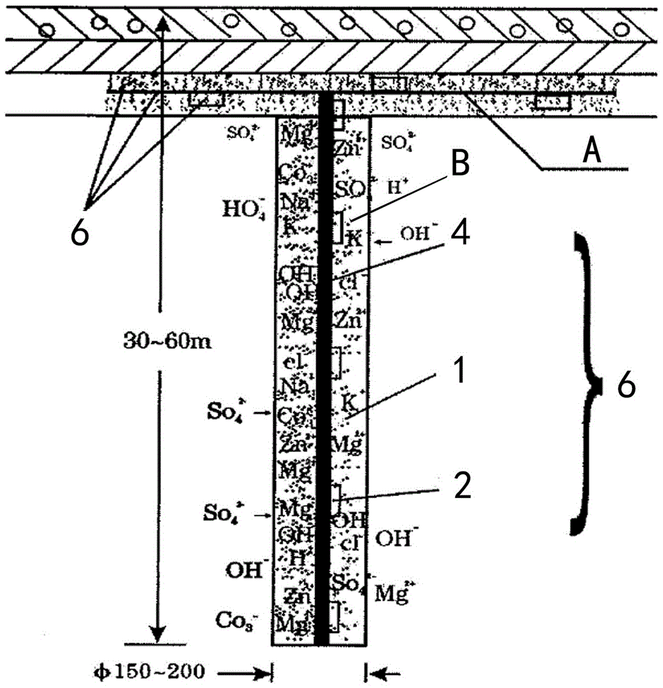
[0071] The invention is an environment-friendly long-term electrolytic ion grounding electrode and its construction method, such as Figure 1-Figure 3 As shown, the electrolytic ion ground electrode 6 of the present invention is a composite ground electrode composed of a steel ground electrode 4, an electrolytic ion source 2, an electrolytic ion carrier 1, and the like. Wherein the electrolytic ion source 2 is the electrolytic ion electrode, the electrolytic ion carrier 1 is wrapped around the steel ground electrode 4 and the electrolytic ion source 2, the electrolytic ion source 2 is connected to the steel ground electrode 4 through the solder joint 3, and one end of the lead wire 5 is connected to the The electrolytic ion source 2 is connected, and the other end of the lead wire 5 is led to the surface. The electrolytic ion source 2 is in the shape of an n-shaped handle, and the handles at both ends of the electrolytic ion source 2 are welded to the steel ground electrode 4 ...
Embodiment 2
[0102] According to the technical requirements of the DL / T475-2006 measurement guideline, the electrolytic ion grounding electrode of the present invention has been developed, field trial, improved and perfected to popularize and apply, and the results show that the overall The resistance reduction effect is remarkable, the resistance value is stable, and no corrosion is seen; the effect is more obvious in rocky mountains and low mountains and hills. The test results are shown in Table 3-Table 10.
[0103] 1. The resistivity test of the resistivity at room temperature is shown in Table 4.
[0104] 2. Physical and chemical performance test
[0105] a. Water loss test: see Table 5 for details.
[0106] b. Cold and hot cycle test: see Table 6 for details.
[0107] c. Water immersion test: see Table 7 for details.
[0108] 3. Impulse current withstand test: see Table 8 for details.
[0109] 4. Power frequency current withstand test: see Table 9 for details.
[0110] 5. Tempe...
Embodiment 3
[0116] When the present invention is actually implemented: the electrolytic ionophore 1 is calculated in parts by weight, bentonite: activator = 50%: 20%, and ordinary water 30%.
PUM
| Property | Measurement | Unit |
|---|---|---|
| Resistivity | aaaaa | aaaaa |
Abstract
Description
Claims
Application Information