Supercharge Your Innovation With Domain-Expert AI Agents!

SOC chip for power grid monitoring and control equipment

A technology for control equipment and power grid monitoring, applied in electrical components, circuit devices, AC network circuits, etc., can solve the problems of low harmonic analysis accuracy, inflexible compensation scheme, and low reactive power compensation control accuracy.

Active Publication Date: 2016-09-21
新唐信通(浙江)科技有限公司
View PDF6 Cites 1 Cited by
  • Summary
  • Abstract
  • Description
  • Claims
  • Application Information

AI Technical Summary

Problems solved by technology

[0004] The purpose of the present invention is to solve the problems of low degree of automation in power quality monitoring, low accuracy of harmonic analysis, low precision of reactive power compensation control and inflexible compensation schemes, and proposes a SOC chip for power grid monitoring and control equipment, including Self-inspection signal source generation module, signal source selection module, three-phase voltage mutual induction module, three-phase current mutual induction module, sampling control module, period measurement module, Beidou communication module, power parameter calculation module, switching capacitor control module, composite switch module , a capacitor bank, a storage module and a self-inspection module, the self-inspection signal source generation module is connected to the three-phase current mutual induction module and the three-phase voltage mutual induction module respectively through the signal source selection module, the three-phase current mutual induction module, the three-phase The voltage mutual induction module is respectively connected with the sampling control module and the period measurement module, the period measurement module is connected with the sampling control module, the sampling control module is connected with the Beidou communication module and the storage module through the power parameter calculation module, and the power The parameter calculation module is connected to the composite switch through the switching capacitor control module, and the composite switch is connected to the capacitor bank

Method used


Image

  • SOC chip for power grid monitoring and control equipment
  • SOC chip for power grid monitoring and control equipment
  • SOC chip for power grid monitoring and control equipment

Examples


Embodiment Construction

[0039] The present invention will be further described in detail below in conjunction with the accompanying drawings and specific embodiments.

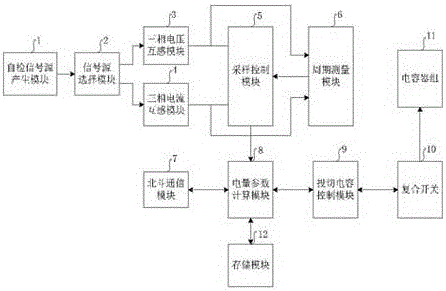
[0040] figure 1 It is a structural schematic diagram of a SOC chip used in power grid monitoring and control equipment of the present invention. The car smart box that realizes real-time identification of road conditions and judgment of danger based on composite sensing includes: self-inspection signal source generation module, signal source selection module, three-phase voltage mutual induction module, three-phase current mutual induction module, sampling control module, period measurement module , Beidou communication module, power parameter calculation module, switching capacitor control module, composite switch module, capacitor bank, storage module and self-inspection module, the self-inspection signal source generation module and the three-phase current mutual induction module respectively through the signal source selection mod...


PUM


Abstract

The invention discloses an SOC chip for power grid monitoring and control equipment. The SOC chip comprises a self-checking signal source generation module, a signal source selection module, a three-phase voltage transformer module, a three-phase current transformer module, a sampling control module, a periodic measurement module, a Beidou communication module, an electric parameter calculation module, a switch capacitor control module, a composite switch module, a capacitor bank, a memory module and a self-checking module. By the method disclosed by the invention, the problems that electric energy quality monitoring automatic degree is low, the harmonic analysis accuracy is low, reactive power compensation control precision is low and the compensation scheme is not flexible are solved; safe operation of a power supply system can be ensured; the electric energy loss is reduced; and the electric energy is saved.

Description

technical field [0001] The invention relates to the technical field of power grid monitoring and control, in particular to a SOC chip for power grid monitoring and control equipment. Background technique [0002] According to the statistics of authoritative organizations, among the line losses of transmission lines, high-voltage distribution network and low-voltage users, the line loss of low-voltage users is the largest. Therefore, loss reduction and energy saving should mainly focus on low-voltage 380V users. For a long time, my country's low-voltage distribution network has weak frame, small wire diameter, aging facilities, large load current, low natural power factor, complex structure, difficult control of voltage quality, and remote transmission of reactive power by the upper-level power grid, which cannot be tracked , reducing the economic benefits of the power grid. A large number of non-linear and impact loads are connected to the power grid, generating harmonics, v...

Claims


Application Information

Patent Timeline
IPC IPC(8): H02J3/18H02J3/01H02J3/00
CPCH02J3/00H02J3/01H02J3/18Y02E40/30Y02E40/40
Inventor 王丹
Owner 新唐信通(浙江)科技有限公司
Features
  • R&D
  • Intellectual Property
  • Life Sciences
  • Materials
  • Tech Scout
  • Unparalleled Data Quality
  • Higher Quality Content
  • 60% Fewer Hallucinations
Learn More