
On-line detection device and method for shield machine tool and cutterhead wear based on optical fiber sensing

A shield machine cutting tool and optical fiber sensing technology, which is applied in the direction of optical testing for flaws/defects, earthwork drilling, instruments, etc. Application of cutter head wear detection and other issues to achieve the effect of avoiding electromagnetic interference design, reducing transmission capacity limit, and small size

Active Publication Date: 2018-10-23
WUHAN UNIV OF TECH
View PDF6 Cites 4 Cited by
  • Summary
  • Abstract
  • Description
  • Claims
  • Application Information

AI Technical Summary

Problems solved by technology

[0007] It is not difficult to find from the existing technology that although this traditional detection technology is direct and effective, there are huge risks in essence. In today's information age, this traditional detection method can no longer keep up with the pace of development of the times
[0008] It is not difficult to find from the existing technology that the application range of these two methods is small, and each detection unit requires a separate circuit, and its monitoring method is difficult to meet the monitoring needs of large capacity, and these two methods are not applied at this stage To the wear detection of the cutter head
[0009] By searching open technical reports, academic papers, invention patents and other documents, no direct monitoring method for shield machine wear detection has been found. The main reasons are as follows: 1) The sensors used for monitoring cannot destroy the normal working state of the shield machine, In addition, the working environment of the shield machine is harsh and complex, and strict requirements are placed on the quality, volume, installation method and sensing type of the sensor; 2) The cutter head of the shield machine is a rotating body, and the sensor on the drum and the sensor signal processing module There are strict requirements on the transmission mode of the sensing signal; 3) The working environment of the shield machine tool and cutter head is harsh and complex, and a large-capacity overall monitoring is required to better characterize the wear of the shield machine

Method used


Image

  • On-line detection device and method for shield machine tool and cutterhead wear based on optical fiber sensing
  • On-line detection device and method for shield machine tool and cutterhead wear based on optical fiber sensing
  • On-line detection device and method for shield machine tool and cutterhead wear based on optical fiber sensing

Examples


Embodiment Construction

[0031] The present invention will be further described below in conjunction with specific examples and accompanying drawings.

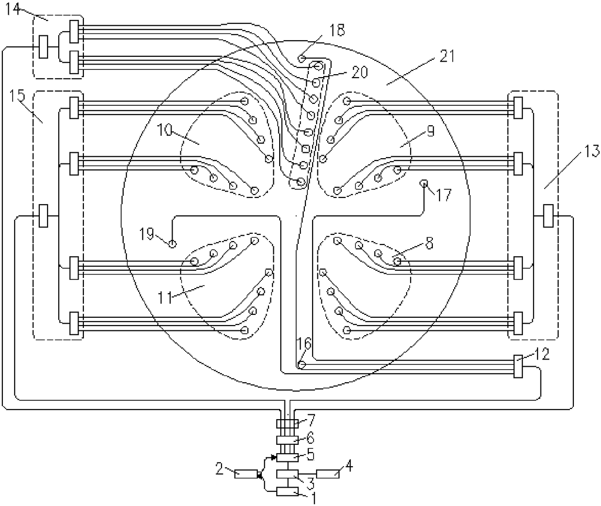
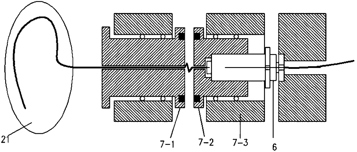
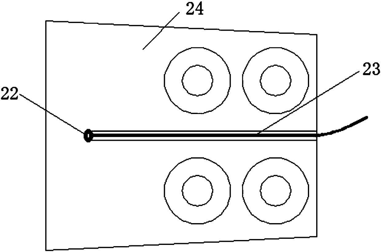
[0032] The invention provides an on-line detection device for shield machine tool and cutterhead wear based on optical fiber sensing, such as Figure 1 to Figure 4 shown, including:

[0033] A fiber grating position sensor group consisting of several fiber grating position sensors 23 with the same structure, each fiber grating position sensor 23 includes a grating on an optical fiber, and each fiber grating position sensor 23 is installed in the deep hole of the device to be detected , and the fiber end of the fiber grating position sensor 23 is located at the wear limit position 22 of the device to be detected; the device to be detected includes a cutting tool 23 to be detected, a wear detection tool 25 and a cutter seat of the cutter head 21;

[0034] The light splitting system is used to transmit light to each fiber grating position sensor 23 resp...


PUM

PropertyMeasurementUnit
reflectanceaaaaaaaaaa

Abstract

The invention provides a shield tunneling machine cutter and cutter head wearing online detection device based on optical fiber sensing. The device comprises a fiber bragg grating position sensor group installed in a deep hole of a device to be detected, a beam splitting system used for transmitting light to each fiber bragg grating position sensor, a demodulating system used for demodulating light returned from each fiber bragg grating position sensor into electric signals, and a control system used for controlling on and off of the beam splitting system, analyzing the electric signals demodulated by the demodulating system, and judging whether any one or more of a cutter, a wearing detection cutter and a cutter head are worn and wearing positions, and the optical fiber end of each fiber bragg grating position sensor is located at the wearing limit position of the device to be detected. By the adoption of the device, the anti-electromagnetic interference design of the sensors is avoided, and no negative affect is caused to the normal working state of the shield tunneling machine cutter and cutter head.

Description

technical field [0001] The invention belongs to the technical field of monitoring the health state of a shield machine, and in particular relates to an on-line detection device and method for wear of a shield machine tool and cutter head based on optical fiber sensing. Background technique [0002] At present, the shield construction method has established a relatively high position in the construction of urban tunnels (such as subway tunnels, sewage discharge tunnels, water diversion, water supply tunnels, rivers and lakes submarine tunnels, electric power, telecommunications, gas supply and common ditch projects, etc.). Some people call it the urban tunneling method. With the success of the first shield tunneling method in Shanghai, attempts and explorations of this construction method have begun in China. The shield machine relies on the cutter on the cutterhead to cut the soil and continuously excavates. During the excavation process, the cutter will inevitably be impac...

Claims


Application Information

Patent Timeline
Patent Type & Authority Patents(China)
IPC IPC(8): G01N21/88E21D9/08
CPCE21D9/08G01N21/88G01N2201/088
Inventor 梁磊冯坤徐刚罗玉文张健吴慧峰李东旭曹珊王慧仇磊涂彬段细云许儒泉
Owner WUHAN UNIV OF TECH
Learn More