
Evaporating system capable of conducting online descaling and working continuously and evaporating process

An evaporation system and process technology, applied in the direction of evaporation, steam pressurized evaporation, evaporator adjustment/control, etc., can solve the problems of heat loss, high operating cost, low utilization rate of system equipment, etc., and achieve the effect of reducing times and costs

Active Publication Date: 2016-10-12
广州中科鑫洲科技有限公司 +1
View PDF7 Cites 7 Cited by
  • Summary
  • Abstract
  • Description
  • Claims
  • Application Information

AI Technical Summary

Problems solved by technology

[0005] (1) The utilization rate of system facilities is low: after the MVR evaporation system stops evaporating and enters the cleaning section, some major equipment must stop working, such as steam compressors, heating systems, steam-water separation systems, etc. It will be equipped with an evaporation pre-treatment system and a post-treatment system. The pre-treatment system refers to a preliminary treatment system such as removing impurities from the raw liquid, and the post-treatment system refers to the recyclable utilization of the evaporation system. Therefore, once the evaporation unit enters the cleaning section, it will cause the MVR evaporation system and its supporting peripheral facilities to stop working, resulting in a low utilization rate of system equipment;
[0006] (2) The effective time of evaporation treatment is short, and the cost of wastewater treatment is high: high-concentration wastewater, such as alcohol wastewater, landfill leachate, coal chemical wastewater, chemical wastewater, pharmaceutical wastewater, biomass cracking wastewater, etc., general scaling (organic and Inorganic scale) is relatively fast, and the evaporation cycle is short, only 8 hours to 12 hours, that is, cleaning at least once a day
Every time the evaporator is cleaned, it needs to be drained and cooled for about 3 hours, cleaned with water and drained for about 0.5 hours, cleaned with acid solution and drained with clean water for about 0.8 hours, cleaned with lye and drained with water Evacuation takes about 0.8 hours, liquid inlet heating and start-up take about 2 hours, and the whole cleaning takes about 7-8 hours. The cleaning time is long, the effective time of wastewater evaporation treatment is short every day, the cost of wastewater treatment is high, and the amount of wastewater treated is far below According to the design requirements, the problem of evaporation fouling has become the main obstacle to the application of evaporation process in wastewater treatment
[0007] (3) Due to the above problems, in the application of MVR evaporation technology in wastewater treatment, not only the cost of unit treatment equipment has doubled, but also the alternation of cold and heat in the evaporation and cleaning switching process of the entire system has resulted in the loss of a large amount of heat energy, resulting in an increase in operating costs.
[0008] In addition, most of the current requirements for industrial wastewater treatment are zero discharge, which requires the full application of the 3C recycling concept in the treatment process to concentrate the wastewater back into the production process or recover valuable substances. It is required that the concentration process can produce concentrates with different concentration ratios Recycling is currently implemented by multiple sets of evaporation processes, and the construction cost and energy consumption are very high

Method used


Image

  • Evaporating system capable of conducting online descaling and working continuously and evaporating process
  • Evaporating system capable of conducting online descaling and working continuously and evaporating process
  • Evaporating system capable of conducting online descaling and working continuously and evaporating process

Examples


Embodiment 1

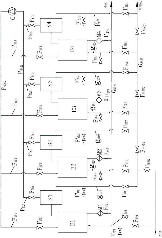
[0080] Such as figure 1 The shown online descaling and continuous working evaporation system is an embodiment of the present invention, which includes a control device (not shown in the figure), an evaporator E, a steam compressor C, a supplementary heat system (not shown in the figure) shown), the steam-water separation tank S, each piping system and the on-off valves on it, wherein each piping system includes a liquid inlet pipe g 进 , Concentrate out of pipe g 出 , condensate outlet pipe, low temperature steam outlet pipe P 低 , high temperature steam into pipe P 高 And evaporator E, as well as washing liquid inlet pipe and washing liquid outlet pipe, are equipped with on-off valves on the piping system. In the inlet pipe g 进 , Concentrate out of pipe g 出 , Condensed water outlet pipe, washing liquid inlet pipe, washing liquid outlet pipe, low temperature steam outlet pipe P 低 and high temperature steam into the pipe P 高 The on-off valves are respectively called: inlet ...

Embodiment 2

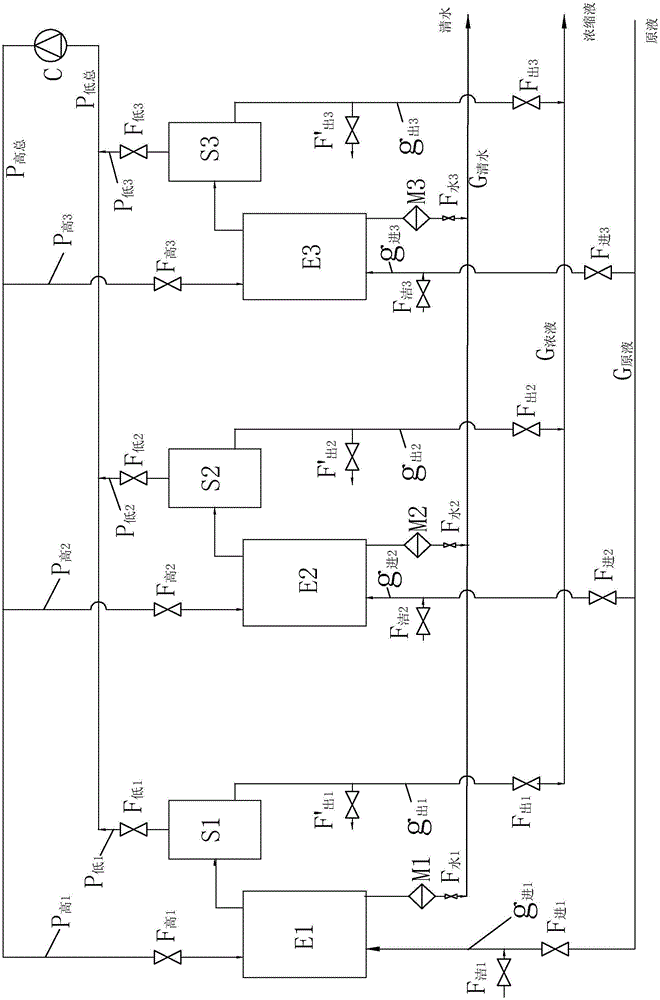
[0092] figure 2 The shown online descaling and continuous working evaporation system is an embodiment of the present invention. The difference from Embodiment 1 is that

[0093] The evaporation system has 3 sets of evaporation units, and the 3 sets of evaporation units are connected in the way of liquid inlet parallel evaporation to form a complete evaporation system. The way of liquid inlet parallel evaporation refers to the 3 inlet pipes on the 3 sets of evaporation units 进 Both are respectively connected with a main liquid pipe G 原液 connected to form parallel mode, such as figure 2 Shown, the first liquid inlet pipe g 进1 , the second liquid inlet pipe g 进2 and the third liquid inlet pipe g 进3 G 原液 Connect so that the liquid inlet pipes of each evaporation unit g 进 Both are connected to the raw liquid and evaporated at the same time, and there is no relationship between the upper and lower stages of concentration between each set of evaporation units.

[0094] When ...

Embodiment 3

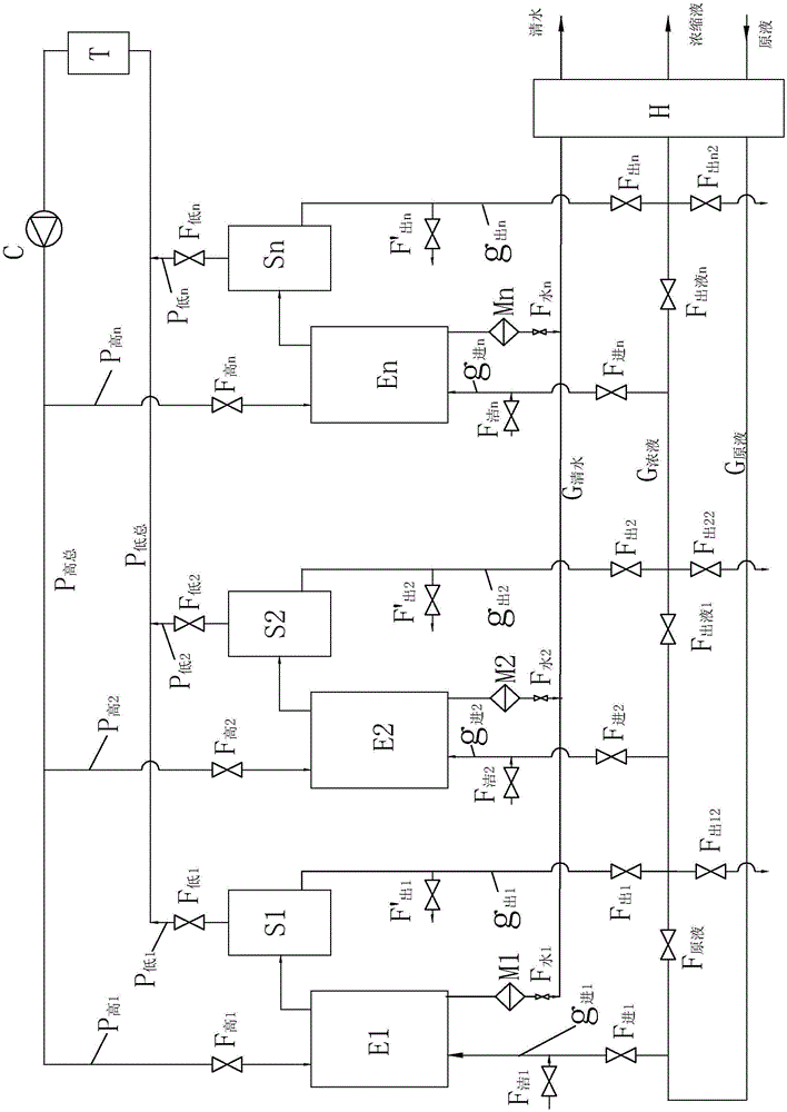
[0096] image 3 The shown online descaling and continuous working evaporation system is an embodiment of the present invention. The difference from Example 1 is that this evaporation system has n sets of evaporation units, and n is a natural number greater than 1. As a preferred implementation Mode n is 2-5.

[0097] Liquid inlet pipe g of the first set of evaporation units in n sets of evaporation units 进 with stock solution manifold G 原液 connection, another set of a concentrate pipe G 浓液 , the concentrated solution of the first set of evaporation unit comes out of the pipe g 出1 with concentrate manifold G 浓液 Connection, the liquid inlet pipes of other sets of evaporation units g 进 and concentrate out of tube g 出 Also connected to the concentrate manifold G 浓液 connection, and the inlet pipe g of each evaporation unit 进 and concentrate out of tube g 出 A concentrated liquid valve F is set on the concentrated liquid main pipe section between 出液 , adopting different ope...


PUM


Abstract

The invention discloses an evaporating system capable of conducting online descaling and working continuously and an evaporating process. The evaporating system comprises n evaporating units, each evaporating unit is composed of an evaporator E and a steam-water separation mechanism S, the n evaporating units are connected in a feed liquor series-connection or parallel-connection evaporation mode to form the complete evaporating system, secondary steam generated by the n evaporating units shares one steam compression machine for pressurization and temperature raising, and a high-temperature steam main pipe is connected out of the steam compression machine and connected to high-temperature steam inlet pipes on the evaporating units in parallel; a liquid inlet pipe of the second-level / set evaporating unit is simultaneously connected with the first-level / set concentrate outlet pipe and a stoste inlet pipe; a concentrate main pipe is arranged, all the evaporating units except the first level / set evaporating unit are connected with the concentrate main pipe, the concentrate main pipe segment between the liquid inlet pipe and the concentrate output pipe of each evaporating unit is provided with a concentrate valve, valves on related inlet pipes and outlet pipes are controlled to isolate the evaporating units to be cleaned, and evaporating work of the system is not affected.

Description

technical field [0001] The invention relates to an evaporation system and an evaporation process, in particular to an evaporation system and an evaporation process capable of online descaling and continuous work. Background technique [0002] Evaporation technology has developed rapidly in the production process of food, chemical industry, pharmaceutical and garbage treatment or waste water treatment. There are two kinds of evaporation technologies: multi-effect evaporation with steam as the main heat source and mechanical vapor compression evaporation with electricity as the main source. Since steam mechanical compression evaporation (MVR) uses the secondary steam to be compressed and heated by the compressor to become an evaporation heat source for evaporation, the heat recovery efficiency is very high, and the heat consumption per ton of water produced by evaporation is generally 5% to 10% of that of the three-effect evaporation system. Therefore, the technology of second...

Claims


Application Information

Patent Timeline
IPC IPC(8): B01D1/28B01D1/00
CPCB01D1/0082B01D1/2887B01D1/2896
Inventor 陈伟雄林顺陈鑫和
Owner 广州中科鑫洲科技有限公司
Learn More