Diversified wind duct circulating power generating station with gradual perpetual motion power and air traction effect

A traction effect and power station technology, applied in wind power generation, photovoltaic power generation, electrical components, etc., can solve the problems of low distribution density of solar radiation energy, difficulty in accurately predicting system power generation, and difficulty in large-scale utilization and high-efficiency utilization. The effect of occupying high-quality land, not affecting climate change, and high-efficiency power generation operation

Inactive Publication Date: 2016-10-12
万金林 +1
View PDF0 Cites 4 Cited by
  • Summary
  • Abstract
  • Description
  • Claims
  • Application Information

AI Technical Summary

Problems solved by technology

[0003] 1. Thermal power plants: heavy pollution, bleak prospects for sustainable development; high energy consumption, low efficiency
[0004] 2. Nuclear power plants: Nuclear power plants will produce high and low-level radioactive waste, or used nuclear fuel. Although the volume is not large, they must be handled carefully due to radiation, and they need to face considerable political troubles
However, there are not suitable winds anytime and anywhere. If the wind is too strong, it cannot be operated; if the wind is too weak, it cannot be operated; the cost of building a wind farm is very high.
[0007] 5. Solar power generation: the energy distribution density of solar radiation is small, about 100W / m2; the annual power generation hours are low, with an average of 1300h; continuous power generation is not possible, and it is greatly affected by weather conditions such as seasons, day and night, and cloudy or sunny; accurate prediction of system power generation It is difficult; the cost of photovoltaic system is relatively high, and the system cost is 40,000-60,000 yuan / kW
Due to its low dispersion and low energy density, biomass energy is difficult to use in a large scale and efficiently, so the economic benefits are poor. This is also the main reason why biomass energy cannot become a commercial energy source at present.

Method used


Image

  • Diversified wind duct circulating power generating station with gradual perpetual motion power and air traction effect
  • Diversified wind duct circulating power generating station with gradual perpetual motion power and air traction effect
  • Diversified wind duct circulating power generating station with gradual perpetual motion power and air traction effect

Examples


example 1

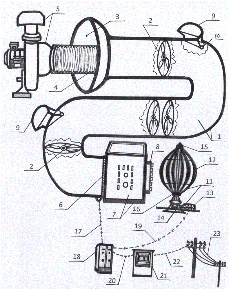
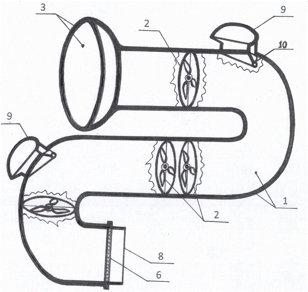
[0024] The air duct (hole) body (1) with an inner diameter of 1.8-5 meters and an inner diameter of 120-2500 meters will be built on the ground or underground; and the inner circumference of the air duct (hole) body (1) is respectively Install some (1.5-4.5 meters in diameter) Nei Nei wind power generators (2); at the front end of the natural wind air inlet (3) of the blower (hole) body (1), install a large air volume blower (5), blower The air outlet (4) is opposite to the natural wind air inlet (3), and the large air volume blower (5) requires a caliber of 0.8-3.8 meters; Carrying out blowing can make air and natural wind enter freely from the natural wind air inlet (3), so as to achieve the effect of natural pressurization and increase wind speed; the power of the large air volume blower (5) is 20-200KW, A high-speed index exhaust fan (7) is installed at the end (6) of the hole) body, and the exhaust fan outlet (8) draws wind speed to the outside of the air cylinder (hole) ...

example 2

[0027] 1. Construct the above-ground or underground multi-stage wind tunnel circulation power station with constant dynamic power and air traction effect. The wind tunnel (hole) body (1) is mainly constructed by mechanical trenching, with a length of 754 meters and a width of 8.8 meters at the top. The bottom is 8.5 meters wide and 3.4 meters deep. After the bottom of the ditch is compacted, make a concrete cushion of 60-120 mm. 2. On the concrete cushion, install 2 rows of cement culvert pipes side by side with a distance of 0.15-0.3 meters between them, and install elbow cement culvert pipes at both ends of the 2 rows of cement culvert pipes so that the two rows of cement culvert pipes form a circular and transparent underground Air duct (hole) body (1) girth is 1508 meters, and whole air duct (hole) body (1) is made waterproof layer and anti-air-permeable layer and is done backfill soil layer and greening ground surface on this layer. 3. The internal wind generator (2) of ...


PUM


Abstract

The invention discloses a diversified wind duct circulating power generating station with gradual perpetual motion power and an air traction effect. The diversified wind duct circulating power generating station with the gradual perpetual motion power and the air traction effect comprises a wind duct (tunnel) body, inner wind-driven power generators, a large-wind-volume wind blower, a high-speed indexing wind exhauster, wind speed and air current defective pressurizing cabin hoppers, a vertical external wind-driven power generator, rotor vanes, a power generator, a gearbox, an upper rotor center, a lower rotor center, an inverter, a power selling machine and the like. Air is adopted as a power generating energy source; the diversified wind duct circulating power generating station with the gradual perpetual motion power and the air traction effect is simple and convenient in process and high-efficiency in running; the problems of energy sources are thoroughly solved; the problems of environment contamination are solved naturally; and meanwhile, the problem of climate warming is also solved. Thus, the goal that the human being enters a carbon-free economical and electric new age with ecological civilization and green development is achieved. The diversified wind duct circulating power generating station with the gradual perpetual motion power and the air traction effect can be fully used as the energy source for all the production and the life of the human being; contaminative thermal power generating plants, nuclear power stations and bio-fuel power generation can be thoroughly eliminated; and the high-input and low-efficacy wind power generation, hydraulic power generation and solar power generation can be eliminated. Thus, the purpose of diversifying wind duct circulating power generation is achieved; and the diversified wind duct circulating power generating station with the gradual perpetual motion power and the air traction effect is extremely complete.

Description

technical field [0001] The invention relates to a step-by-step constant dynamic power and air traction effect multiple air duct cycle power station in the field of power generation. More specifically, it is especially related to the use of air as energy for power generation. The use of air energy can be used as energy for all production and life of all human beings, completely eliminate polluting thermal power plants, nuclear power plants, and biofuel power generation, and eliminate low-efficiency wind power. Power generation and solar power generation and all power stations that are inefficient and harmful to the environment and climate. The use of air as power generation energy has a simple process and high-efficiency operation, which completely solves the energy problem of human beings, naturally solves the problem of environmental pollution, and also solves the problem of climate warming. In order to realize the new era of electrification of human beings towards ecologica...

Claims


Application Information

Patent Timeline
Patent Type & Authority Applications(China)
IPC IPC(8): F03D9/25F03D9/37F03D3/06
CPCF03D3/06F03D3/062F03D9/255F03D9/37F05B2240/91H02S20/20F03D9/00Y02E10/50Y02E10/72Y02E10/728Y02E10/74Y02P70/50
Inventor 万金林曲广生
Owner 万金林
Why Eureka
Try Eureka