
Integrated system based on film generating, energy storage and luminescence

An integrated system and thin film technology, which is applied in the field of new energy development and application, can solve the problems of high energy consumption in the preparation process, high manufacturing cost, inflexibility of inorganic solar devices, etc., and achieve the effect of avoiding the loss of light intensity

Inactive Publication Date: 2016-10-26
SHANGHAI UNIV
View PDF4 Cites 7 Cited by
  • Summary
  • Abstract
  • Description
  • Claims
  • Application Information

AI Technical Summary

Problems solved by technology

[0003] At present, inorganic solar cells represented by silicon (SI) occupy the main market of solar cells. This type of solar cell is expensive to manufacture, consumes a lot of energy in the preparation process, and needs to use more toxic chemicals and water resources. Solar devices are inflexible and cannot be bent. The narrow bandgap characteristics of inorganic semiconductor materials make them severely photocorroded, which seriously affects the service life of inorganic solar cells.

Method used


Image

  • Integrated system based on film generating, energy storage and luminescence
  • Integrated system based on film generating, energy storage and luminescence

Examples


Embodiment 1

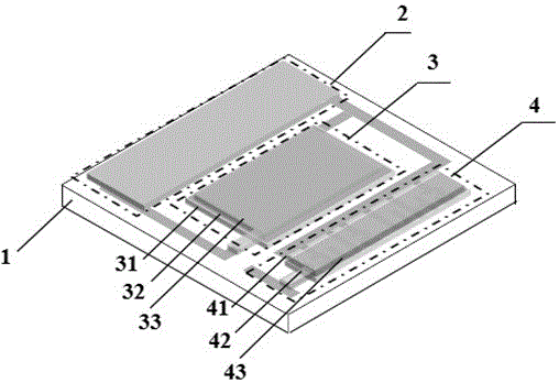
[0022] refer to figure 1 , an integrated system based on thin film power generation, energy storage, and light emission, including: substrate (1), capacitor (2), OPV device (3), super and OLED light emitting device (4). It is characterized in that: the substrate (1), the supercapacitor (2), the OPV device (3) and the OLED light-emitting device (4) are integrated on the same plane of the same substrate.

Embodiment 2

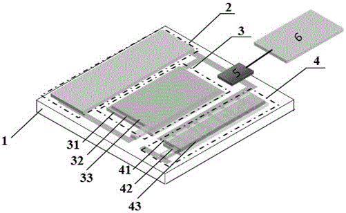
[0024] This embodiment is basically the same as Embodiment 1, and the special features are as follows: the substrate (1) is a glass substrate or a PET flexible substrate. The OPV device (3) uses thin-film technology, and the substrate (1) is sequentially composed of an OPV anode (31), an OPV organic functional layer (32), and an OPV cathode (33) from inside to outside. The OPV device (3) selects one or more of ITO, ZnO, FTO, GZO, graphene, and graphene / carbon nanotube composite film as a transparent anode, and selects one of Au / Ag alloy, Al, and ITO One or more as a transparent or translucent cathode. The supercapacitor (2) uses thin film technology, which is made by inkjet printing, printing and other processes. The OLED light-emitting device (4) uses thin-film technology, and consists of an OLED anode (41), an OLED organic functional layer (42), and an OLED cathode (43) sequentially from the inside to the outside of the substrate. The OLED light-emitting device (4) is a fl...

Embodiment 3

[0026] In this example, see figure 1 , an integrated system based on thin film power generation, energy storage, and light emission, including a glass substrate (1), a supercapacitor (2), an OPV device (3), an OPV anode (31), an OPV organic functional layer (32), and an OPV cathode (33), OLED light-emitting device (4), OLED anode (41), OLED organic functional layer (42), OLED cathode (43).

[0027] In this embodiment, an integrated system based on thin-film power generation, energy storage, and light emission includes: a substrate, an OPV device on the same plane as the substrate, an OLED light-emitting device, and a supercapacitor connecting the OPV device and the OLED light-emitting device. The OPV device adopts an upright structure, from the inside to the outside of the substrate, there are OPV anode, OPV organic functional layer, and OPV cathode. The OLED light-emitting device adopts a bottom emission structure, and the OPV device and OLED light-emitting device adopt a co...


PUM


Abstract

The invention belongs to the field of new energy development and application, and relates to an integrated system based on film generating, energy storage and luminescence. The integrated system comprises a substrate, an OPV device, a supercapacitor and an OLED, wherein the OPV device, the supercapacitor and the OLED are integrated on the same plane of the substrate. Light is irradiated on the OPV device, generated electric energy is stored in the supercapacitor, and the supercapacitor can be applied to driving the OLED to emit light and can also be taken as a portable power supply apparatus. According to the invention, the OPV device, the OLED and the supercapacitor are connected, such that light intensity loss caused by absorption of light by the OPV device can be avoided, and the system can also be applied to a flexible technology.

Description

technical field [0001] The invention belongs to the field of new energy development and application, and in particular relates to an integrated system based on thin film power generation, energy storage and light emission. Background technique [0002] The solar radiation received by the earth every year is about 5.44x1024J, which is equivalent to 10,000 times the annual consumption of human beings. As the best solar energy utilization component, solar cells are devices that generate electricity through the photovoltaic effect of materials. [0003] At present, inorganic solar cells represented by silicon (SI) occupy the main market of solar cells. This type of solar cell is expensive to manufacture, consumes a lot of energy in the preparation process, and needs to use more toxic chemicals and water resources. Solar devices have no flexibility and cannot be bent, and the narrow bandgap characteristics of inorganic semiconductor materials make them severely photocorroded, whi...

Claims


Application Information

Patent Timeline
Patent Type & Authority Applications(China)
IPC IPC(8): H01L51/42H01G11/00H01L51/50H01L25/16
CPCH01L25/167H01G11/00H10K30/00H10K50/00Y02E10/549Y02E60/13Y02P70/50
Inventor 魏斌杨连乔陈章福司长峰祝俊刘诗琦
Owner SHANGHAI UNIV
Learn More