Injection molding machine

An injection molding machine and injection molding technology, applied in the direction of coating, etc., can solve the problems of reduced strength of finished products, low production efficiency, and increased processing difficulty, and achieve the effects of reducing equipment costs, reducing production efficiency, and improving processing efficiency

Active Publication Date: 2016-11-02
宁波伯乐智能机械有限公司
View PDF6 Cites 0 Cited by
  • Summary
  • Abstract
  • Description
  • Claims
  • Application Information

AI Technical Summary

Problems solved by technology

Composite reinforcing fibers are often used in injection molding products to increase the structural strength of injection molding products. However, there are four main application forms of composite reinforcing fibers that have matured at present. One is the hand lay-up method. Reinforced fiber sheets are sheared and laminated, or resin is applied while laying layers, and then hot-pressed. The strength of the composite reinforced fiber product made by this method is high, but the production efficiency is low; The reinforcing fiber monofilament is wound on the fiber shaft, this method is only suitable for making cylinders and hollow vessels, and the production efficiency is low; one is the molding method, this method is to put the composite reinforcing fiber material pre-impregnated with resin into In the metal mold, the excess glue is overflowed after being pressurized, and then solidified at high temperature. The strength of the composite reinforced fiber product made by this method is high, but the production efficiency is also low, and structural parts cannot be made; one is long fiber In the raw material injection molding method, the composite reinforcing fiber is preprocessed to make raw materials, and then injection molded by an injection molding machine. Although this method solves the problem of production efficiency, the fibers with longer fiber lengths in the raw materials pass through the screw of the injection molding machine and the hot runner. Under the action of shearing and heating, only 30% of the finished products have a fiber length of more than 5mm, resulting in a greatly reduced strength of the finished product
[0003] Due to the complex structure of some injection molding products, one-time injection molding cannot be realized, and it needs to be processed in steps, and when producing and processing injection molding products with complex structures, if they need to meet the high-strength requirements at the same time, the processing difficulty will increase exponentially
[0004] In order to improve the strength of injection molded products, it is very necessary to add composite reinforcing fibers, but at the same time, when processing composite reinforcing fiber materials, the strength of composite reinforcing fiber materials is easily damaged at high temperatures, and the length of the fibers And its interlacing complexity in the finished product will affect the strength of its finished product

Method used


Image

  • Injection molding machine
  • Injection molding machine
  • Injection molding machine

Examples


Embodiment 1

[0032] As with the above-mentioned injection molding machine, this embodiment differs from it in that the compounding structure is used for shearing and melting different forms of materials to be processed;

[0033] The material to be processed includes: fibers and raw materials, the lengths of the fibers include continuous fibers and short fibers, and the fibers include carbon fibers;

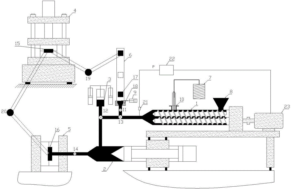
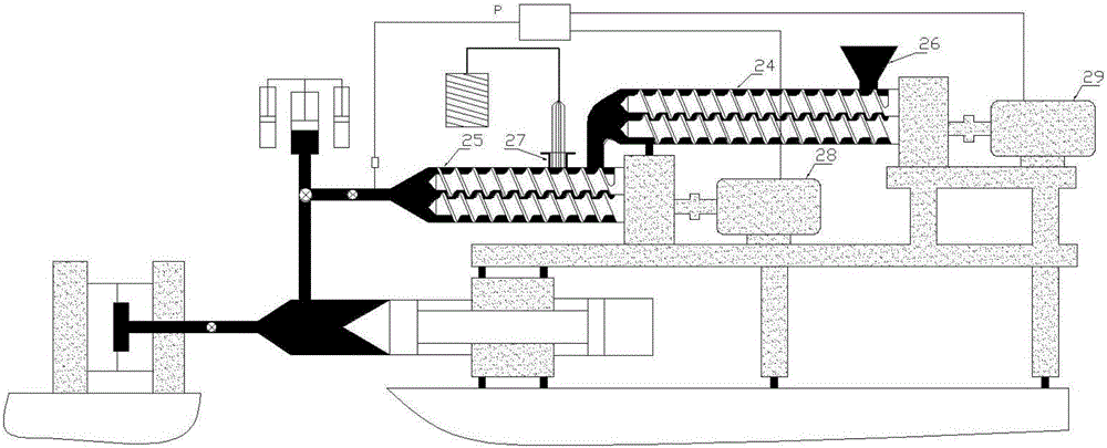
[0034] The compounding structure includes: a motor 23 and an extruder 1; the motor 23 is used to provide power for the compounding process, the output shaft of the motor 23 is connected with the input end of a reducer, and the reducer The output end of the speed reducer is connected with the extruder 1, and a screw assembly is arranged inside the extruder 1. Driven by the reducer, the screw assembly rotates around the axis direction; the screw assembly includes at least It is composed of a screw, and at least one kind of helix is ​​arranged on the screw. When the material to be processed moves...

Embodiment 2

[0038] As the above-mentioned injection molding machine, this embodiment differs from it in that, such as figure 1 As shown, the storage and injection conversion structure includes a storage cylinder 3, a storage and injection hydraulic cylinder, and a storage and injection gate valve 12;

[0039] Since the compounding structure works in a continuous feeding state, the injection melt will be continuously extruded, while the injection structure is in an intermittent working state, and there is a period of injection and pressure holding time in each molding cycle. Therefore, it is necessary to provide a temporary storage space for the continuously supplied injection molding melt, so that the injection molding melt can flow all the time when it is continuously supplied from the compounding structure, so as not to block the equipment, thereby preventing the equipment from being blocked. The continuous feeding of the compounding structure is realized, and the production efficiency ...

Embodiment 3

[0045] Like the above-mentioned injection molding machine, this embodiment differs from it in that the injection structure is used to complete the injection process of the injection melt, which includes an injection barrel 2 , an injection push rod and an injection gate valve 14 . The injection barrel 2 is used to store a certain amount of injection molding melt. When the injection molding melt injected into the injection barrel 2 reaches the set amount, the storage gate valve 12 stops the injection molding melt from flowing down, and the injection pushes The rod pushes the injection melt out through the injection gate valve 14 .

[0046] The injection plunger is placed inside the injection barrel 2 , and the outer diameter of the injection plunger is consistent with the inner diameter of the injection barrel 2 and is a clearance fit.

[0047] The injection gate valve 14 is opened during injection molding and closed during material storage, so as to prevent the melt from being...


PUM


Abstract

The invention discloses an injection molding machine used for machining injection-molded products. The injection molding machine is particularly used for conducting mold pressing machining on to-be-machined injection-molded products containing fiber materials. The injection molding machine comprises an injection molding machine body used for conducting forming mold pressing. The injection molding machine further comprises a double-extruder type mixing structure used for fusing and shearing to-be-machined materials. The double-extruder type mixing structure comprises a first extruder and a second extruder. The second extruder is located at the downstream position of the first extruder. A second material inlet is formed in the second extruder and used for putting in the fiber materials. The injection molding machine further comprises a pre-machining structure used for conducting preliminary forming on the to-be-machined injection-molded products. The pre-machining structure comprises a mold head used for manufacturing a blank, and a mold press used for manufacturing a mold pressing pre-formed product. The pre-machining structure is arranged, and integral machining and forming are conducted on the injection-molded products of the complex structure form.

Description

technical field [0001] The invention relates to the field of injection molding machines, in particular to an injection molding machine. Background technique [0002] Composite reinforced fiber is a fiber material with a series of excellent properties such as high specific strength, high specific modulus, high temperature resistance, corrosion resistance, fatigue resistance, radiation resistance, electrical conductivity, heat transfer, and low relative density. performance fibers. Composite reinforcing fibers are often used in injection molded products to increase the structural strength of injection molded products. However, there are mainly four mature application forms of composite reinforcing fibers. One is the hand lay-up method, which combines the dipped composite fiber. Reinforcing fiber sheets are laminated in scissor shape, or brushed with resin while laying layers, and then hot-pressed. The composite reinforced fiber product made by this method has high strength, b...

Claims


Application Information

Patent Timeline
IPC IPC(8): B29C45/00B29C45/53B29C45/58B29C47/40B29C47/56
CPCB29C45/0005B29C45/53B29C45/58B29C48/402B29C48/49B29C45/23B29C45/28B29C45/5008B29C45/561B29C2045/237
Inventor 刘玉鹏张洪邹涛沈明聪邹骞
Owner 宁波伯乐智能机械有限公司
Why Eureka
Try Eureka