Biomass steam boiler system

A biomass boiler and steam boiler technology, applied in the field of boilers, can solve the problems of difficulty in meeting the needs of actual use of boilers, high energy consumption in boiler operation, and low operating efficiency, and achieve the goals of reducing emissions, generating steam quickly, and reducing energy The effect of consumption

Inactive Publication Date: 2016-11-09
TIANJIN YUEMING METAL STRUCTURE CO LTD
View PDF5 Cites 3 Cited by
  • Summary
  • Abstract
  • Description
  • Claims
  • Application Information

AI Technical Summary

Problems solved by technology

[0002] The boiler is a kind of energy conversion equipment. The energy input to the boiler includes chemical energy and electric energy in the fuel. The boiler outputs steam, high-temperature water or organic heat carrier with certain heat energy. The hot water or steam generated in the boiler can be directly used for industrial production. To provide the required heat energy for people’s lives, among which the steam boiler is called a steam boiler. The steam boiler is one of the important equipment for people to obtain high-temperature steam and water in a centralized manner. It plays an irreplaceable role in the fields of heating, gas supply, and water supply. When steam boilers operate, they often mainly rely on burning coal, oil and other resources to drive the boiler operation, resulting in high energy consumption for

Method used


Image

  • Biomass steam boiler system

Examples


Embodiment Construction

[0023] The core of the present invention is to provide a biomass steam boiler system, which can reduce energy consumption during steam boiler operation, reduce pollutant discharge, and realize energy saving and emission reduction.

[0024] The following will clearly and completely describe the technical solutions in the embodiments of the present invention with reference to the accompanying drawings in the embodiments of the present invention. Obviously, the described embodiments are only some, not all, embodiments of the present invention. Based on the embodiments of the present invention, all other embodiments obtained by persons of ordinary skill in the art without making creative efforts belong to the protection scope of the present invention.

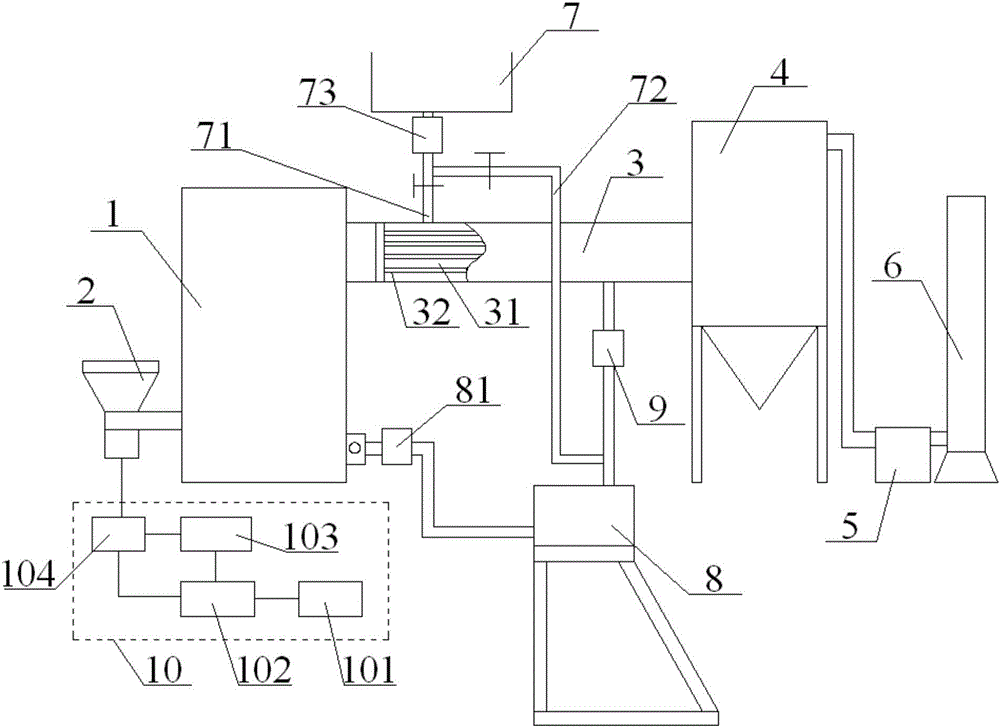
[0025] Please combine figure 1 , figure 1 It is a schematic structural diagram of the biomass steam boiler system provided by the present invention.

[0026] The biomass steam boiler system provided by the present invention inclu...


PUM


Abstract

The invention discloses a biomass steam boiler system. The biomass steam boiler system comprises a biomass boiler, a biomass fuel conveyer, a smoke heat exchanger, a cloth bag type dust collector, an induced draft fan, a smoke discharge pipe, a water source, a solar collector, a first pump and a solar power supply system, wherein the smoke heat exchanger is connected with the smoke outlet of the biomass boiler and is provided with a heat exchanging water storage cavity; the cloth bag type dust collector, the induced draft fan and the smoke discharge pipe are sequentially connected to the smoke heat exchanger; the water source is connected with the water filling port of the water storage cavity through a first branch pipe; the water inlet of the solar collector is connected with the water outlet of the water storage cavity, and the water outlet of the solar collector is connected with the water filling port of the biomass boiler; the first water pump is arranged between the water storage cavity and the solar collector; the solar power supply system is connected with the power supply of the conveying mechanism of the biomass fuel conveyer. During the operation of the boiler, cold water is sequentially heated by the water storage cavity of the smoke heat exchanger and the solar collector and then enters the boiler, energy consumption during steam boiler operation can be lowered, the cloth bag type dust collector can purify smoke and reduce pollutant emission, and energy conservation and emission reduction are achieved.

Description

technical field [0001] The invention relates to the technical field of boilers, in particular to a biomass steam boiler system. Background technique [0002] The boiler is a kind of energy conversion equipment. The energy input to the boiler includes chemical energy and electric energy in the fuel. The boiler outputs steam, high-temperature water or organic heat carrier with certain heat energy. The hot water or steam generated in the boiler can be directly used for industrial production. To provide the required heat energy for people’s lives, among them, the boiler that generates steam is called a steam boiler. The steam boiler is one of the important equipment for people to obtain high-temperature steam and water in a concentrated manner. It plays an irreplaceable role in the fields of heating, gas supply, and water supply. When steam boilers operate, they often mainly rely on burning coal, oil and other resources to drive the boiler operation, resulting in high energy con...

Claims


Application Information

Patent Timeline
IPC IPC(8): F22B31/08F22D1/00F23J15/02F24J2/00
CPCY02E10/40F22B31/08F22D1/003F23J15/022F24S21/00
Inventor 王俊月
Owner TIANJIN YUEMING METAL STRUCTURE CO LTD
Why Eureka
Try Eureka