
Concrete gravity dam deformation optical fiber sensing monitoring technology and concrete gravity dam deformation optical fiber sensing monitoring system

A gravity dam and sensing technology, applied in the direction of measuring devices, optical devices, instruments, etc., can solve the problem that the process structure mechanism is not suitable for large-volume concrete high dam projects, etc., to improve the effectiveness and technological level, without electromagnetic interference , The effect of fast performance improvement

Inactive Publication Date: 2016-11-09
SICHUAN UNIV
View PDF2 Cites 12 Cited by
  • Summary
  • Abstract
  • Description
  • Claims
  • Application Information

AI Technical Summary

Problems solved by technology

[0009] To sum up, it is easy to see that for concrete gravity dam projects, the existing method of directing optical fibers into concrete for slender members such as piles and beams is obviously not suitable for large-volume concrete high dam projects in terms of technology and structural mechanism.

Method used


Image

  • Concrete gravity dam deformation optical fiber sensing monitoring technology and concrete gravity dam deformation optical fiber sensing monitoring system
  • Concrete gravity dam deformation optical fiber sensing monitoring technology and concrete gravity dam deformation optical fiber sensing monitoring system
  • Concrete gravity dam deformation optical fiber sensing monitoring technology and concrete gravity dam deformation optical fiber sensing monitoring system

Examples


Embodiment Construction

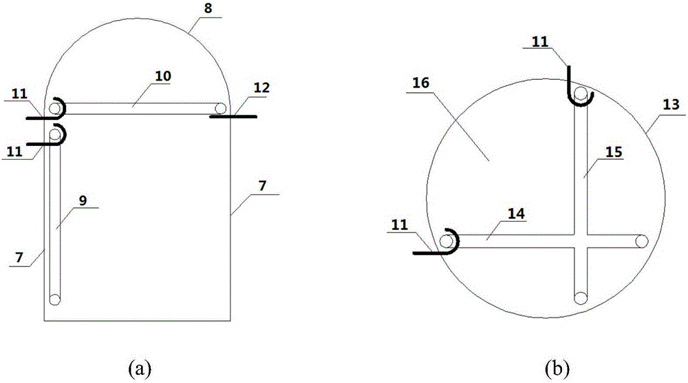
[0052] (1) The laying and installation of the optical fiber monitoring board in the corridor: figure 2 (a), the vertical monitoring board (for observing the vertical displacement and horizontal displacement and joints in the transverse direction) is installed close to the upstream (or downstream) side wall of the corridor, and the top is fixed with expansion bolts (or embedded parts). The horizontal monitoring plate (to observe the longitudinal and transverse horizontal displacement and joints of each dam section along the way) is installed at the bottom of the roof arch of the corridor, and its upstream side is fixed with expansion bolts, and the downstream side is supported by steel strips to form a simple support. The total station is used for control and measurement during the installation work to ensure accurate positioning and leveling, and to ensure the levelness of the top of the vertical plate and the horizontal plate; the installation of the joints between the plate ...


PUM


Abstract

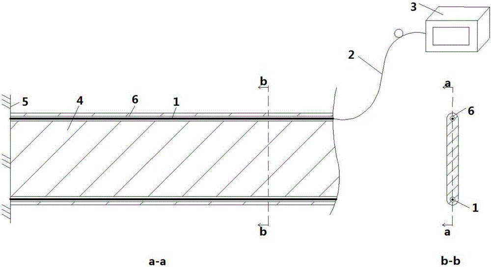
The invention discloses a distribution-type optical fiber sensing system and a technical scheme, which are used to realize integrated on-line remote measurement of dam body-batholith internal deformation three components of a gravity dam, a dam body joint, and diastrophism, cracking, and extrusion of a bedrock tectonic belt, and is used to realize dam multidimensional-large scale spacetime full coverage. A plate-shaped beam of a novel optical fiber packaging structure---narrow rectangular section is provided, and the tension-compression sides of the plate-shaped beam are provided with microtubes to form an Euler elastic beam, and then the force-light direct conversion of the optical fiber is realized. An arrangement type of a sensing system in the gallery and the vertical shaft of the dam-bedrock, the comprehensive use of the sensing system, and an optical fiber laying technology are provided. The multifunctional integration of the optical fiber monitoring is achieved, construction is facilitated, the survival rate of the optical fiber is guaranteed, and application is convenient. An optical signal demodulation device adopts a high precision PPP-BOTDA or a hybrid Brillioun-Rayleigh system, and is multifunctional for being used for projects of monitoring a concrete temperature-reservoir water temperature, a slit position in front of a dam(factory), and a reservoir slit, and other optical fiber monitoring projects, and therefore upgrading and updating of a safety monitoring system are prompted.

Description

technical field [0001] The invention relates to a distributed optical fiber sensing monitoring system and technical scheme for the deformation of a concrete gravity dam, which can realize the distributed optical fiber sensing online monitoring of the internal deformation of the concrete gravity dam body and dam foundation. Background technique [0002] So far, the internal deformation monitoring of concrete gravity dams and their dam foundations has commonly used shallow tension method, laser alignment, vertical line method, static level, inclinometer tube, steel wire displacement meter and so on. Among them, some equipment requires manual on-site operation, such as active inclinometers, laser alignment, etc., and it is difficult to achieve real-time online telemetry; most equipment needs to be measured by electrical measuring equipment such as coordinate instruments; The working hours are still unsatisfactory; they are often arranged in typical dam sections, which cannot be...

Claims


Application Information

Patent Timeline
IPC IPC(8): G01B11/16
CPCG01B11/16
Inventor 陈江刘浩吾孙曼王琛唐天国
Owner SICHUAN UNIV
Learn More