Dielectric resonator filter antenna

A dielectric resonator and filter antenna technology, which is applied in high-gain dielectric resonator filter antennas, antennas, compact, broadband fields, can solve the problems of serious loss, low antenna gain, filter loss, etc., and achieve improved stopband suppression, The effect of low antenna loss and wide stopband

Inactive Publication Date: 2016-11-09
SOUTH CHINA UNIV OF TECH
View PDF5 Cites 9 Cited by
  • Summary
  • Abstract
  • Description
  • Claims
  • Application Information

AI Technical Summary

Problems solved by technology

Although the collaborative design of the filter and the antenna improves the module performance to a certain extent, the loss of the filter is unavoidable, especially when multi-order resonators are required, which often leads to more serious loss, which leads to a relatively low gain of the antenna
[0004] At this stage, there are few antenna designs that can have a good filtering effect without using complex filtering circuits

Method used


Image

  • Dielectric resonator filter antenna
  • Dielectric resonator filter antenna
  • Dielectric resonator filter antenna

Examples


Embodiment Construction

[0025] The implementation of the present invention will be further described below in conjunction with the accompanying drawings and examples, but the implementation and protection scope of the present invention are not limited thereto.

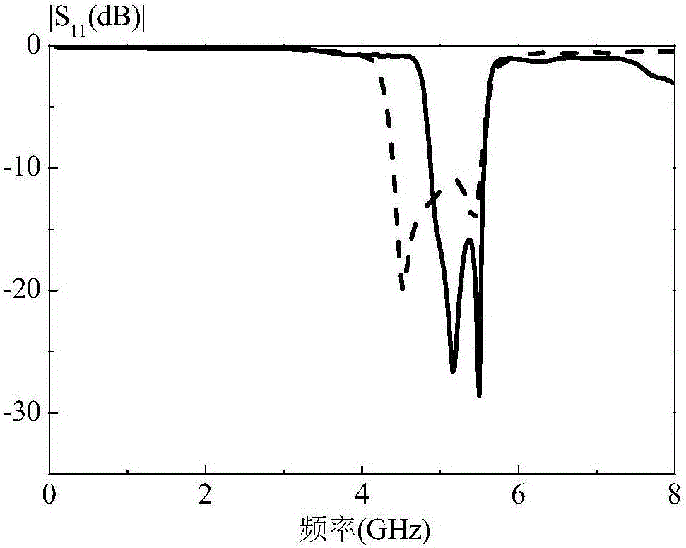
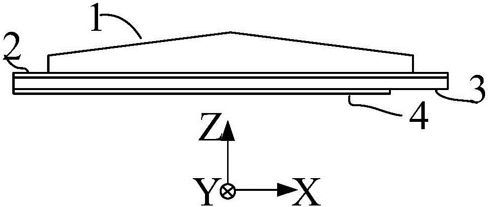
[0026] By way of example only, a broadband, high gain dielectric resonator filter antenna operating at 5 GHz. figure 1 A side view of the antenna of this embodiment. Dielectric resonator 1 of the present embodiment adopts relative permittivity ε r =10 dielectric material processing, the wedge shape at the top is beneficial to reduce the radiation side lobe. The height of the upper spire is 4mm, the thickness of the lower part is h=3mm, the length l=63mm, and the width w=40mm; the thickness of the dielectric substrate 3 is h 1 = 0.813 mm of RO4003.

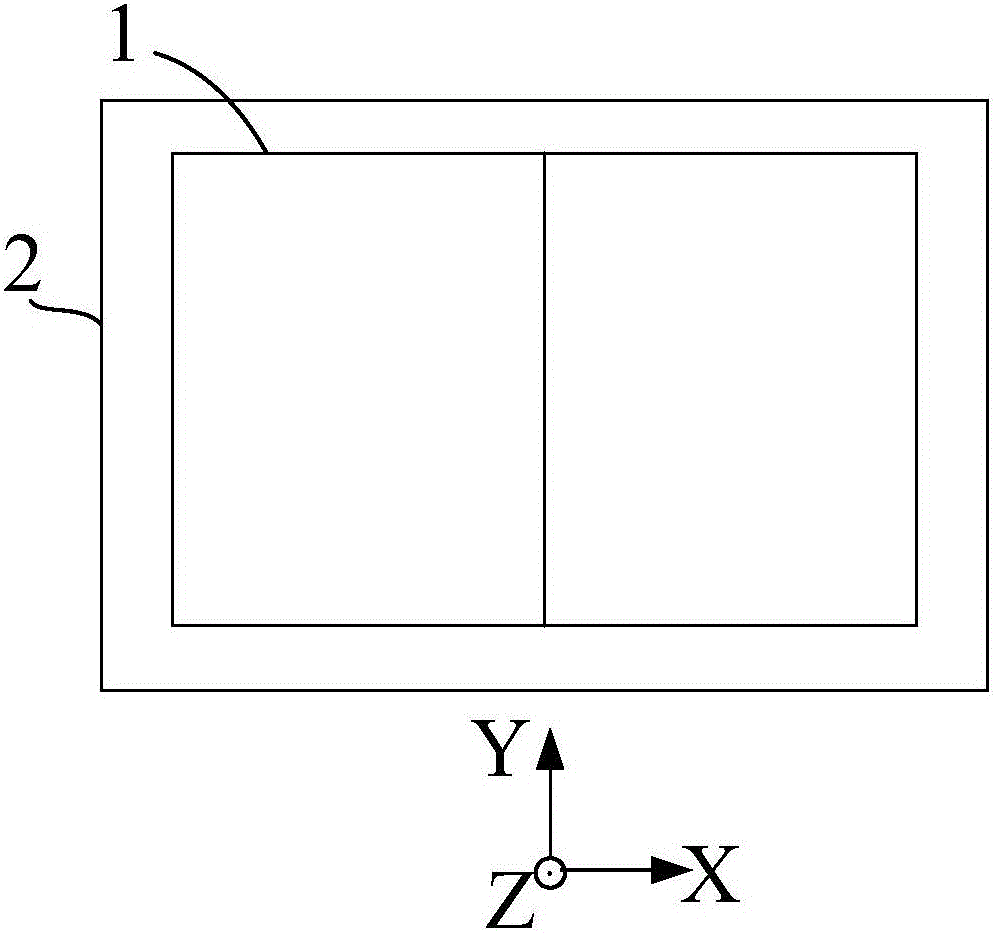
[0027] figure 2 is a top view of this embodiment. refer to image 3 , the floor 2 of this embodiment, that is, the upper surface of the dielectric substrate 3 . The two slots 5 are mirror-...


PUM


Abstract

The invention discloses a dielectric resonator filter antenna. The antenna is fed from the bottom part through microstrip-coupled slots and simultaneously stimulates three modes to generate a wide radiation passband; and a wedge-shaped dielectric resonator antenna is stimulated by a pair of interval slots to improve the gain. An open circuit branch of a feed microstrip line can provide two radiation zero points close to the edge of the passband; parasitic microstrip lines are added to two sides of the feed microstrip line in parallel to improve the out-of-band rejection level of a high-frequency stop band; and the coupled slots are separated from the middle to improve the out-of-band rejection level of a low-frequency stop band. The dielectric resonator filter antenna has a quasi-elliptic function band-pass response, is simple in structure and does not utilize a complicated filter circuit. The designed 10dB impedance bandwidth can reach 23%; the band average gain is 9.05dBi; and the out-of-band rejection within a wide stopband range exceeds 25dB. Different bandwidth characteristics (13%-23%) can also be achieved through adjusting the antenna size.

Description

technical field [0001] The invention relates to an antenna in the field of wireless mobile communication, in particular to a compact, wide-band, high-gain dielectric resonator filter antenna applicable to radio frequency terminals such as mobile communication base stations. Background technique [0002] In wireless communication systems, integrated modules have attracted much attention. Antennas and filters are two integral components of an RF front end. Usually, the antenna and filter are designed independently as two components, and then they are respectively matched to 50Ω standard ports, and then the two are cascaded. In this way, the size of the entire module is increased, which is unfavorable for a radio frequency front-end with limited space. And because the bandwidths of the filter and the antenna are often not exactly the same, the filtering effect is affected. To overcome these problems, filter and antenna integration as a module is proposed. [0003] Most of t...

Claims


Application Information

Patent Timeline
Patent Type & Authority Applications(China)
IPC IPC(8): H01Q1/48H01Q1/50H01Q1/38
CPCH01Q1/48H01Q1/38H01Q1/50
Inventor 潘咏梅胡鹏飞章秀银
Owner SOUTH CHINA UNIV OF TECH
Why Eureka
Try Eureka