Scintillator plate for ray detection flat detector and preparation method for the same

A flat-panel detector and ray detection technology, applied in radiation intensity measurement and other directions, can solve the problem of detection performance of detectors without etched array units, and achieve the effects of low maintenance cost, long service life, and improved system imaging resolution

Active Publication Date: 2016-11-23
SHANGHAI INST OF CERAMIC CHEM & TECH CHINESE ACAD OF SCI +1
View PDF22 Cites 12 Cited by
  • Summary
  • Abstract
  • Description
  • Claims
  • Application Information

AI Technical Summary

Problems solved by technology

Chinese patents CN 1034101C, CN1995274A, and CN 103380194A all report patents on garnet ceramics or single crystal scintillators, but their shortcomings lie in the scintillation performance of the material and the matching of back-end related electronics. Pomegranate has not been used before. Precedent of Radiation Detection Flat Panel Detector Prepa

Method used


Image

  • Scintillator plate for ray detection flat detector and preparation method for the same
  • Scintillator plate for ray detection flat detector and preparation method for the same
  • Scintillator plate for ray detection flat detector and preparation method for the same

Examples


preparation example Construction

[0070] On the other hand, the present invention also provides a method for preparing the transparent ceramic scintillator plate, comprising: preparing a transparent ceramic scintillator by using a solid-phase reaction method or a liquid-phase method combined with ceramic sintering technology according to the chemical composition of the transparent ceramic scintillator; The prepared transparent ceramic block is processed and cut into a scintillator of a certain size; the transparent ceramic scintillator and the substrate material are fixed through a reflective layer; the multilayer composite structure is polished to a certain thickness; and the composite structure is The scintillator layer is cut into rectangular arrays.

[0071] The preparation method of the transparent ceramic used in the scintillator layer includes:

[0072] (1) Preparation of raw material mixed powder;

[0073] In one example, according to the chemical composition of the transparent ceramic scintillator (L...

Embodiment 1

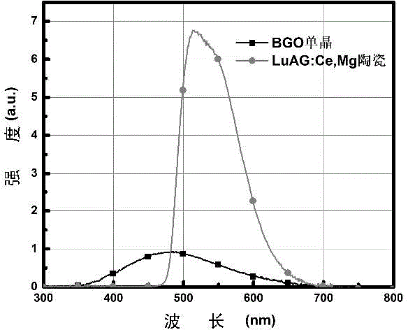
[0100] Using lutetium oxide (Lu 2 o 3 ), alumina (Al 2 o 3 ), magnesium oxide (MgO), cerium oxide (CeO 2 ) as raw material, according to (Lu 0.995 Ce 0.003 Mg 0.002 ) 3 al 5 o 12 Composition Accurately weigh 60g of the powder raw material, and then use absolute ethanol as the dispersion medium for ball milling and mixing. After ball milling for a certain period of time, the two powders are dried and sieved respectively; then they are pressed into tablets and subjected to 200MPa cooling etc. Static pressure into a green body; then put it into a vacuum or hot-press sintering furnace at 1880 ° C for 20 hours to obtain (Lu (1-x-y) Ce x Mg y ) 3 al 5 o 12 Ceramics, the resulting ceramic material is polished to obtain transparent ceramics with high optical quality. The transparent ceramics were ground, polished and cut to 20×20×2 mm. The linear transmittance of the transparent ceramic reaches 73% at 800nm, and the luminous intensity reaches 7.5 times that of BGO sing...

Embodiment 2

[0102] When preparing the scintillator plate, the thickness of the scintillator layer was 50 μm, but laser cutting was not performed, and other conditions were the same as in Example 1. The flat-panel detector adopts the lead wire-to-card method to test the MTF at 10lp / mm, and the MTF is 13.0%. The knife-edge method is used to test the RQA5 experimental conditions specified in the standard IEC62220-1. When the MTF is 10%, the resolution is 6lp / mm.


PUM

PropertyMeasurementUnit
Thicknessaaaaaaaaaa
Thicknessaaaaaaaaaa
Thicknessaaaaaaaaaa

Abstract

The invention discloses a scintillator plate for a ray detection flat and a preparation method for the same. The scintillator plate comprises a substrate, a scintillator layer and a reflection layer clamped between the substrate and the scintillator layer; a composition chemical formula of the scintillator layer is (Lu(1-x-y)CexAy)3Al5O12; available ions for A case comprise at least one of Ca2+, Mg2+, Sr2+, Ba2+, Li+, Na+, and K+, 0.001<=x<=0.05, 0.0005<=y<=0.05. The (Lu,A)3Al5O12:Ce transparent ceramic ray flat detector has characteristics of high imaging sharp spatial resolution, low maintenance cost and long service life, and can be applied to devices using ray detection for medical diagnosis, nondestructive tests, public security, radiation dose detection, petroleum exploration, etc.

Description

technical field [0001] The invention belongs to the field of ray scintillator detector imaging devices, and in particular relates to a scintillator plate in a flat panel detector for ray detection and a preparation method thereof. The detector uses a scintillator plate to convert rays (or particles) such as γ-rays, β-rays or X-rays into visible light, and the visible light excites the photoelectric conversion device to generate current, which is then imported into the computer and converted into graphic information to realize the spatial distribution of rays. Digital photography. The detector using the scintillator plate can be applied to devices using radiation detection such as medical diagnosis, non-destructive detection, public safety, radiation dose detection and oil exploration. Background technique [0002] Radiation detection and imaging technology is widely used in many fields of production and life, such as medical imaging, industrial non-destructive testing, and ...

Claims


Application Information

Patent Timeline
IPC IPC(8): G01T1/20
Inventor 胡辰冯召东石云秦秀波刘书萍李江寇华敏潘裕柏冯锡琪郭景坤
Owner SHANGHAI INST OF CERAMIC CHEM & TECH CHINESE ACAD OF SCI
Why Eureka
Try Eureka