Dust removing device and flue gas dust removing method
A dust removal device, flue gas technology, applied in separation methods, chemical instruments and methods, electrostatic effect separation, etc., to achieve the effects of controlling corrosion, avoiding reduction, and avoiding service life
- Summary
- Abstract
- Description
- Claims
- Application Information
AI Technical Summary
Problems solved by technology
Method used
Image
Examples
Embodiment 1
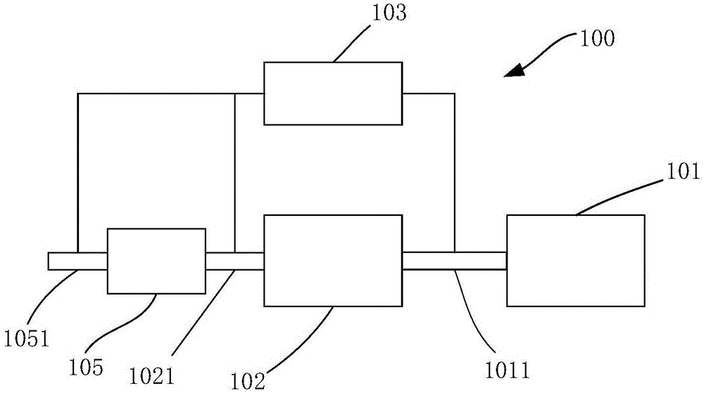
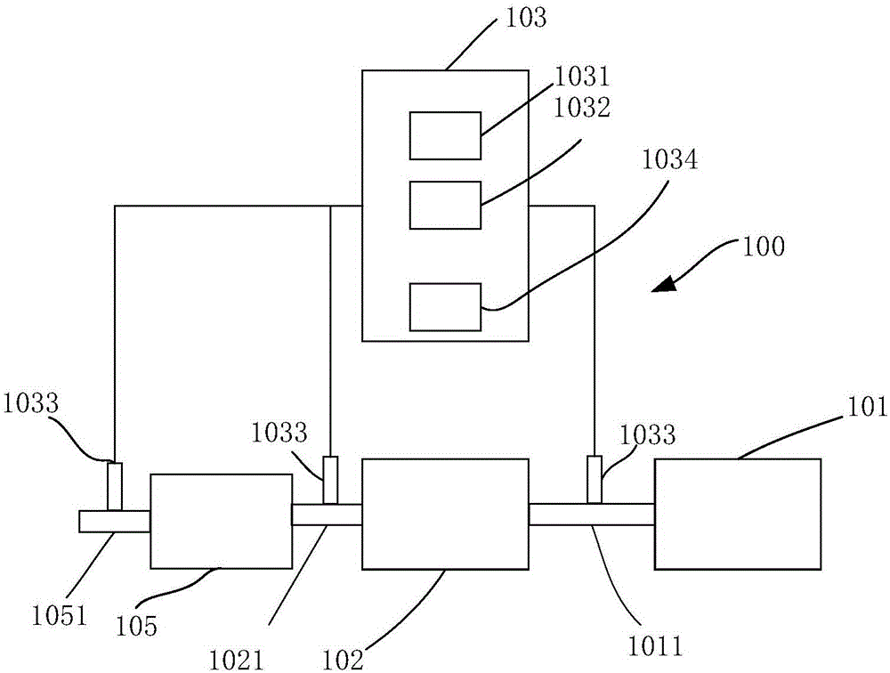
[0040] Such as figure 1 As shown, the present invention provides a dust removal device 100, including an electric precipitator 101, a cooler 102 connected to the inlet section 1011 of the electric precipitator, an alkaline absorbent injection system 103, and the alkaline absorbent injection The injection ports of the system 103 are arranged on the cooler inlet section 1021 . The alkaline absorbent fully absorbs SO3 in the flue gas entering the cooler 102, and when the flue gas is cooled, it prevents the formation of excessive acid mist, thereby reducing the adhesion of acid mist and dust, and avoiding equipment blockage. Furthermore, in order to more fully absorb the acid mist and prevent the acid mist from corroding the equipment in the dust collector, the injection port of the alkaline absorbent injection system 103 can also be arranged on the inlet section 1011 of the electrostatic precipitator. In order to ensure the reliability of the supply of alkaline absorbents and en...
Embodiment 2
[0048] Such as figure 1 As shown, the dust removal device of the present invention includes an electric precipitator 101, a cooler 102 connected to the inlet section 1011 of the electric precipitator, and an alkaline absorbent injection system 103, and the injection port of the alkaline absorbent injection system 103 is set On the inlet section 1021 of the cooler, in this embodiment of the present invention, calcium hydroxide powder is used as the alkaline absorbent, and the cooler 102 is an air preheater or a dust collector smoke cooler, and the dust collector The air precipitator is arranged at the front end of the electrostatic precipitator, and the air preheater is arranged at the front end of the electrostatic precipitator. The air preheater performs heat exchange on the flue gas, which reduces energy consumption, and the strong oxidation Calcium is injected in front of the air preheater or in front of the smoke cooler of the precipitator to reduce SO3 to below 5PPM, and ...
Embodiment 3
[0052] Such as figure 1 As shown, the dust removal device in the embodiment of the present invention includes an electric precipitator 101, a cooler 102 connected to the inlet port 1011 of the electric precipitator, an alkaline absorbent injection system 103, and the alkaline absorbent injection system 103 The injection port is arranged on the inlet section of the cooler 102, such as Figure 6 As shown, the dedusting device 300 in the embodiment of the present invention also includes a destocking reactor (SCR) 305, and the cooler 102 in the embodiment of the present invention is Figure 6 The air preheater 302 in the air preheater 302, the alkaline absorbent can be injected into the SCR reactor outlet section 3052 before the air preheater 302 after the SCR reactor 305, and can also be set on the air preheater before the dust collector 301 after the air preheater 302 On the outlet section 3021 of the SCR reactor, in order to reduce the SO3 content entering the SCR reactor 305,...
PUM
 Abstract
Description
Claims
Application Information
 - R&D
- Intellectual Property
- Life Sciences
- Materials
- Tech Scout
- Unparalleled Data Quality
- Higher Quality Content
- 60% Fewer Hallucinations
Browse by: Latest US Patents, China's latest patents, Technical Efficacy Thesaurus, Application Domain, Technology Topic, Popular Technical Reports.
© 2025 PatSnap. All rights reserved.Legal|Privacy policy|Modern Slavery Act Transparency Statement|Sitemap|About US| Contact US: help@patsnap.com


