
Air compression device of electrical oil-free main air compressor

A technology of air compression and air compressor, which is applied in the direction of machines/engines, mechanical equipment, liquid variable capacity machinery, etc., which can solve the problems of high daily maintenance costs, oil leakage and oil leakage of air compressors, etc., and improve the service life , reduce noise, prevent vibration and noise

Active Publication Date: 2016-12-07
RUILI GROUP RUIAN AUTO PARTS CO LTD
View PDF13 Cites 4 Cited by
  • Summary
  • Abstract
  • Description
  • Claims
  • Application Information

AI Technical Summary

Problems solved by technology

[0004] The main purpose of the present invention is to solve the problems of high daily maintenance cost, oil leakage and oil leakage of the air compressor existing in the current oil-free main air compressor, and provide an oil-free main air compressor that can improve the quality of compressed air and reduce daily maintenance costs. Maintenance cost, electric oil-free main air compressor air compression device that can completely solve the hidden dangers of air compressor oil leakage and oil leakage

Method used


Image

  • Air compression device of electrical oil-free main air compressor
  • Air compression device of electrical oil-free main air compressor
  • Air compression device of electrical oil-free main air compressor

Examples


Embodiment 1

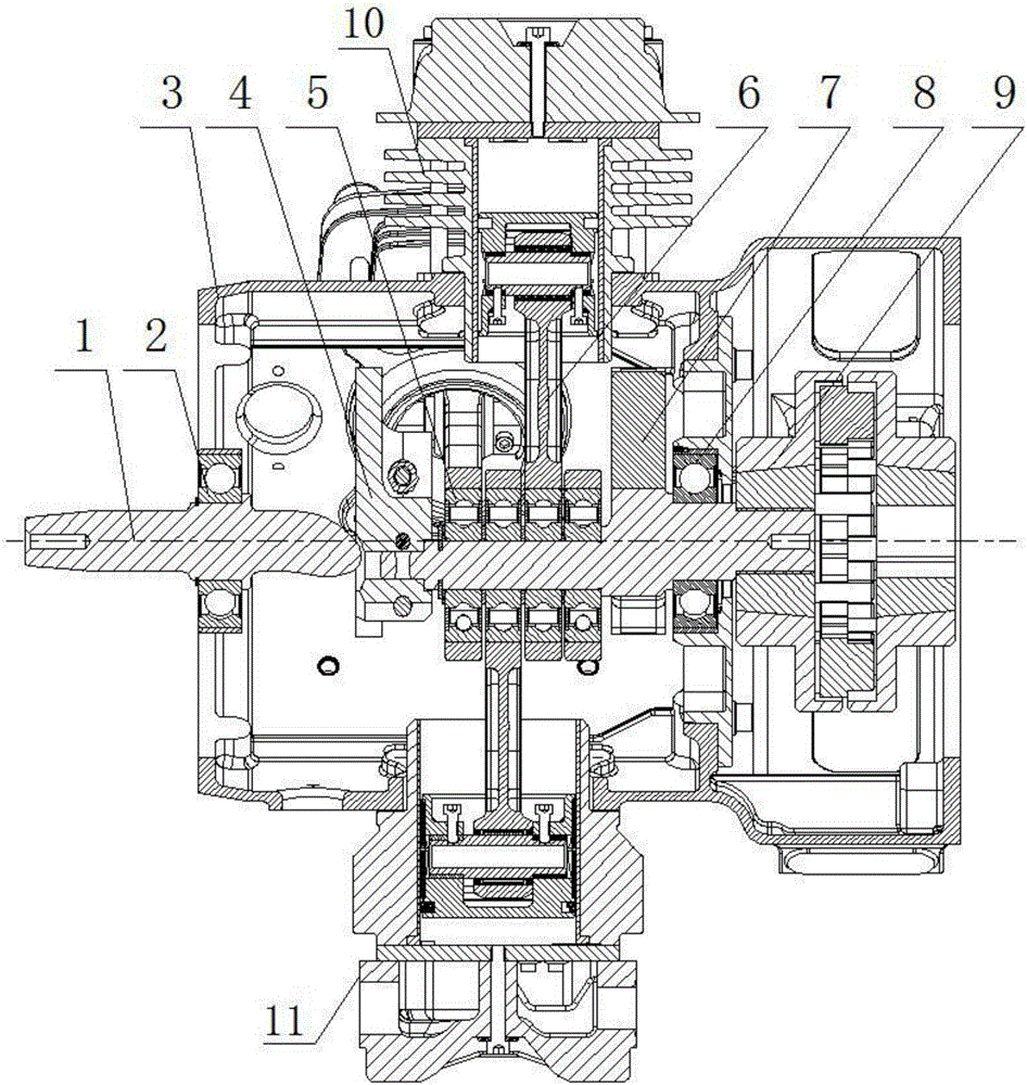
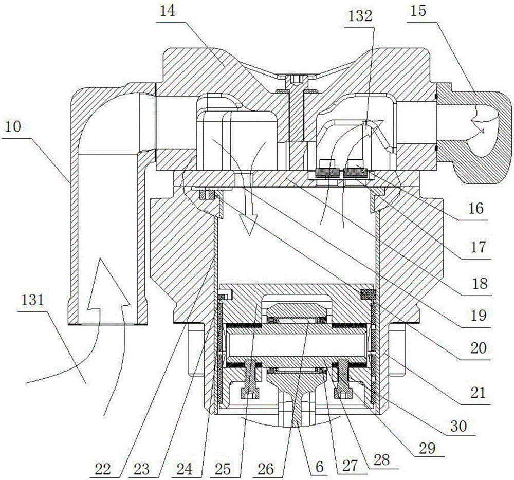
[0039] Such as figure 1 , figure 2 and image 3 As shown, the air compression device of the electric oil-free main air compressor of the present embodiment 1 includes an integral main casing 3 and a compression cylinder assembly arranged on the main casing 3 and connected to the inside of the main casing 3, the main casing Body 3 is provided with crankshaft 1, fan end bearing 2, large counterweight 4, swing rod bearing 5, swing rod 6, small counterweight 7, motor end bearing 8 and shaft coupling 9; the compression cylinder assembly consists of a low-pressure cylinder Cover 14, output joint 15, valve plate screw 16, exhaust reed 17, valve plate 18, intake reed 19, low-pressure cylinder body 21, and pad 20 set in low-pressure cylinder body 21, low-pressure cylinder Cylinder liner 22, piston ring 23, support ring 24, low-pressure piston 25, connecting rod small end bearing 26, oil seal 27, piston pin 28, heat insulating ring 29, compression screw 30; piston ring 23 and support...

Embodiment 2

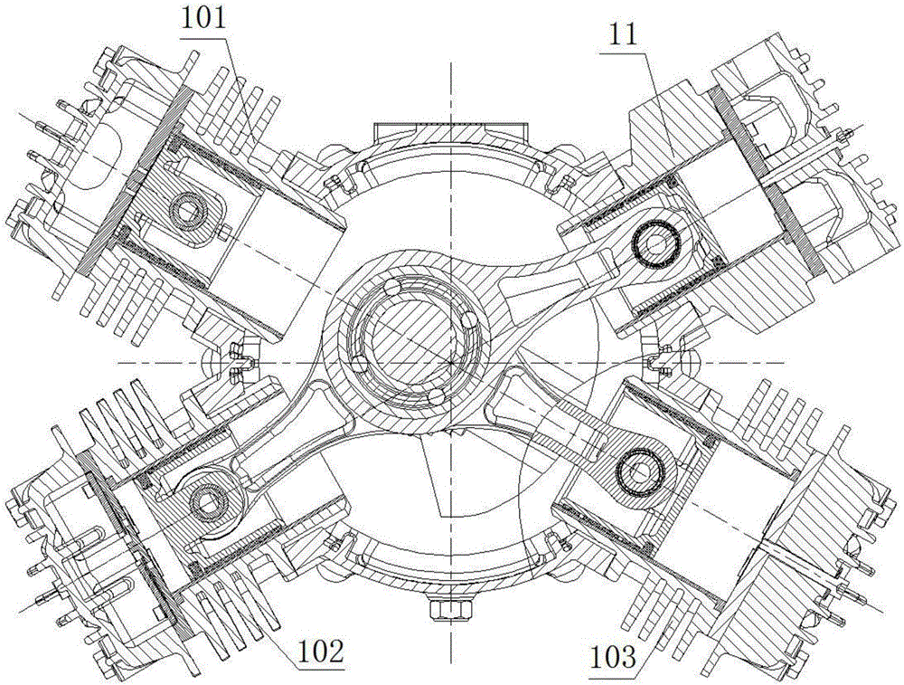
[0051] The main features of this embodiment 2 are: the compression cylinder assembly is composed of two high-pressure cylinder assemblies 11 and two low-pressure cylinder assemblies 10, and the two high-pressure cylinder assemblies 11 and two low-pressure cylinder assemblies 10 are X-shaped on the main housing 3 set up. All the other features are with embodiment 1.

[0052] In Example 1 and Example 2, as figure 1 and image 3 As shown, the rotation of the motor transmits the torque to the coupling 9, and then drives the crankshaft 1 to rotate. The fan end bearing 2 and the motor end bearing 8 provide support and fixation for the crankshaft 1. The rods 6 are all installed in this turning groove. When the crankshaft 1 rotates, the four swing rods 6 will move up and down. The swing rod bearings 5 ​​provide support and fixation for the swing rods 6. The large counterweight 4 and the small counterweight 7 are Provide force balance during the movement of the main body of the air ...


PUM


Abstract

The invention discloses an air compression device of an electrical oil-free main air compressor, and belongs to the technical field of air compressors. The air compression device comprises a main housing, a crankshaft, a fan end bearing, a large counterweight block, a swinging rod bearing, a swinging rod, a small counterweight block, a motor end bearing, a coupler and a compression cylinder component; the compression cylinder component consists of a low-pressure cylinder cover, an output connector, a valve plate screw, an exhaust reed, a valve plate, an air inlet reed, a low-pressure cylinder body, a cushion block, a low-pressure cylinder sleeve, a piston ring, a supporting ring, a low-pressure piston, a connecting rod small end bearing, an oil seal, a piston pin, a heat insulation ring and a compression screw; the compression cylinder component consists of at least one high-pressure cylinder component and at least two low-pressure cylinder components; the piston ring and the supporting ring are made of teflon; the oil seal avoids leakage of bearing grease; the heat insulation ring insulates heat of the low-pressure piston. Oil leakage and blow-by hidden dangers of the air compressors are eliminated through air cooling, and a reasonable air flow trend is formed. With the adoption of the piston ring and the supporting ring that are made of teflon, no oil cooling is required, and the maintenance cost is reduced.

Description

technical field [0001] The invention relates to an air compression device, in particular to an electric oil-free main air compressor air compression device, which belongs to the technical field of air compressors. Background technique [0002] The oil-free air compressor is the main body of the air source device. It is a device that converts the mechanical energy of the prime mover (usually an electric motor) into gas pressure energy. Oil generally refers to the oil content of the gas discharged from the exhaust port of the air compressor. Generally, the oil content of the machine with oil is relatively large, and the oil content of the oil-free air compressor is 0.01ppm, and the other is the oil-free air compressor. Machine, it is not lubricated by oil, but lubricated by resin material, so the final exhaust gas does not contain oil, which is called oil-free air compressor, but in the past, this kind of air compressor was easy to lose the sealed grease, which caused the bear...

Claims


Application Information

Patent Timeline
Patent Type & Authority Applications(China)
IPC IPC(8): F04B25/00F04B35/04F04B39/00
CPCF04B25/00F04B35/04F04B39/00F04B2201/0205
Inventor 达利欧蒋伟荣李传武张玄张仕锡林衍飞
Owner RUILI GROUP RUIAN AUTO PARTS CO LTD
Learn More