Ultrashort pulse carrier-envelope phase detection device and method

A carrier envelope phase and ultrashort pulse technology, which is applied in the field of photoelectric detection, can solve the problems affecting the accuracy of carrier envelope phase signals, the limitation of carrier envelope phase accuracy, and the limitation of optical comb control accuracy, etc., to achieve carrier envelope The phase signal is accurate, the detection sensitivity is improved, and the electronic circuit noise is low.

Active Publication Date: 2016-12-07
UNIV OF SHANGHAI FOR SCI & TECH
View PDF4 Cites 8 Cited by
  • Summary
  • Abstract
  • Description
  • Claims
  • Application Information

AI Technical Summary

Problems solved by technology

Since the ultrashort pulse is affected by various nonlinear effects and the external environment in the detection process in the process of power amplification, supercontinuum broadening, and self-reference beat frequency, it is inevitable to introduce phase noise and affect the carrier envelope phase. The accuracy of the signal causes the control accuracy of the optical comb to be limited
[0004] Therefore, the existing self-referencing f-2f detection system based on ultrashort pulse power amplification, supercontinuum broadening and optical frequency doubling introduces large phase noise, complex detection methods, and limited carrier envelope phase accuracy, which limits Application of Optical Frequency Combs as High-Precision Frequency Standards for Measurements Outside the Laboratory

Method used


Image

  • Ultrashort pulse carrier-envelope phase detection device and method
  • Ultrashort pulse carrier-envelope phase detection device and method
  • Ultrashort pulse carrier-envelope phase detection device and method

Examples


Embodiment 1

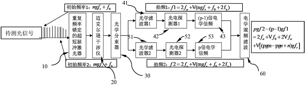
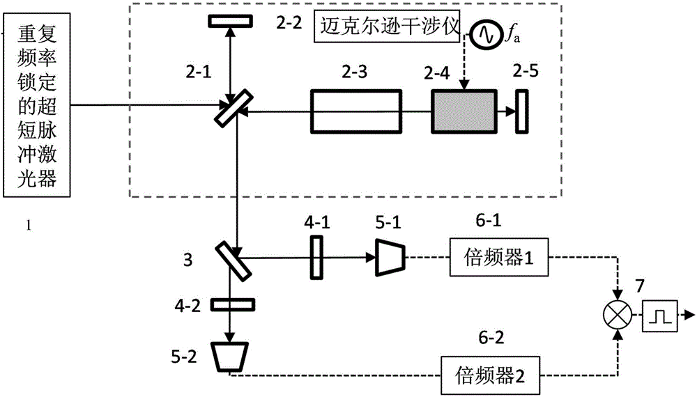
[0035] figure 2 Schematic diagram of the structure of the detecting device for the carrier envelope phase of the ultrashort pulse carrier in the first embodiment.

[0036] Combine below figure 2 The specific structure of the detection device for the ultrashort pulse carrier envelope phase of the spatial structure of this embodiment will be described.

[0037] The detection device of the ultrashort pulse carrier envelope phase of the space structure includes a repetition rate locked ultrashort pulse laser 1, a space structure Michelson interferometer 2, an optical beam splitter 3, and a first optical filter 4-1 , the second optical filter 4-2, the first photodetector 5-1, the second photodetector 5-2, the multiple is the first electrical frequency multiplication unit 6-1 of 2 times, the multiple is the second of 3 times Electrical frequency multiplication unit 6-2, electrical frequency mixing and filtering unit 7.

[0038] The ultrashort pulse laser selects the ytterbium-d...

Embodiment 2

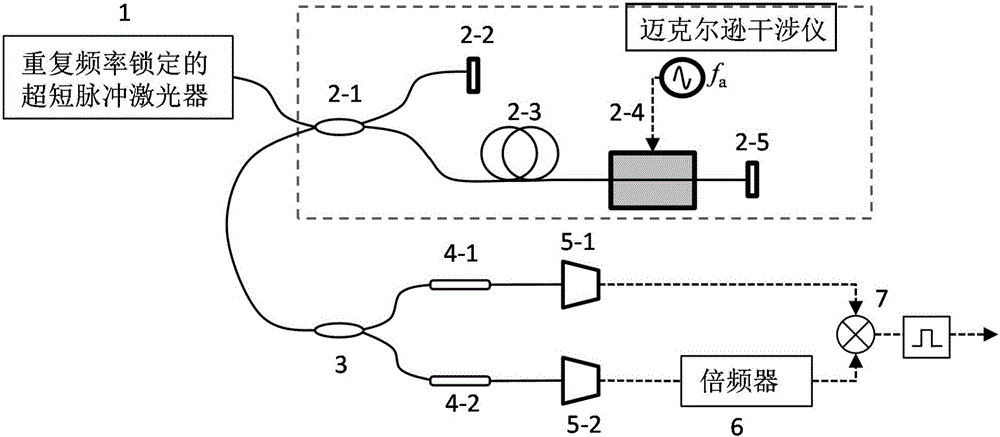
[0044] image 3 Schematic diagram of the structure of the detection device for the ultrashort pulse carrier envelope phase of the fiber structure in the second embodiment.

[0045] Combine below image 3 The specific structure of the detecting device for the ultrashort pulse carrier envelope phase of the optical fiber structure of this embodiment will be described.

[0046] The detection device of the ultrashort pulse carrier envelope phase of the fiber structure includes a repetition rate locked ultrashort pulse laser 1, a Michelson interferometer 2 with an all-fiber structure, an optical beam splitter 3, and a first optical filter 4- 1. The second optical filter 4-2, the first photodetector 5-1, the second photodetector 5-2, the electrical frequency multiplication unit 6 with a multiple of 2, and the electrical frequency mixing and filtering unit 7.

[0047] Ultrashort pulse laser 1 selects an erbium-doped fiber laser with a center wavelength of 1550nm, a spectral range of...

Embodiment 3

[0053] Figure 4 A schematic structural diagram of a feedback-type high-precision ultrashort pulse carrier envelope phase detection device according to Embodiment 3 of the present invention.

[0054] Combine below Figure 4 The specific structure of the feedback-type high-precision ultrashort pulse carrier envelope phase detection device of this embodiment will be described.

[0055] The feedback-type high-precision ultrashort pulse carrier envelope phase detection device includes a repetition rate locked ultrashort pulse laser 1, an all-fiber Michelson interferometer 2, an optical beam splitter 3, and a first optical filter 4-1, the second optical filter 4-2, the first photodetector 5-1, the second photodetector 5-2, the electrical frequency multiplication unit 6 with a multiple of 2, and the first electrical frequency mixing and filtering unit 7 , the second electrical mixing and filtering unit 8 .

[0056] The ultra-short pulse laser selects the erbium-doped fiber laser ...


PUM


Abstract

An ultrashort pulse carrier-envelope phase detection device comprises an ultrashort pulse laser of a fixed repetition frequency, a michelson interferometer, an optical beam splitter, a first optical filter, a first photoelectric detector, a first electrical frequency doubling unit, a second optical filter, a second photoelectric detector, a second electrical frequency doubling unit, and an electrical frequency mixing and filtering unit. The ultrashort pulse laser, the michelson interferometer and the optical beam splitter are in light path connection in order. The first optical filter, the first photoelectric detector, and the first electrical frequency doubling unit with a multiple of (p-1) are connected with a first output end of the optical beam splitter. The second optical filter, the second photoelectric detector, and the second electrical frequency doubling unit with a multiple of p are connected with a second output end of the optical beam splitter. The electrical frequency mixing and filtering unit is connected with output ends of the first electrical frequency doubling unit and the second electrical frequency doubling unit. The modes of time domain time delay and frequency domain selection are adopted, front and back pulses delayed for a certain period are subjected to coherent detection with the michelson interferometer, two different frequency windows are used for frequency domain selection, signals representing carrier-envelope phase jitter are extracted, and measurement of the ultrashort pulse carrier-envelope phase signals are achieved by electrical frequency doubling and frequency mixing processes.

Description

technical field [0001] The invention belongs to the field of photoelectric detection technology, and in particular relates to a detection device and method for an ultrashort pulse carrier envelope phase. Background technique [0002] Optical frequency comb generation and control technology is a frontier topic in the field of scientific research in recent years. By actively controlling the repetition frequency and carrier envelope phase of ultrashort pulses, a comb-shaped frequency standard with a completely stable frequency mode is obtained, which has high precision and wide range. It brings breakthrough precision improvement in precision spectrum, laser ranging, clock transmission, astronomical comparison and other applications. [0003] The repetition frequency of ultrashort pulses can be directly measured by a photodetector with a bandwidth that meets the requirements, and its control technology is currently very mature. High-precision repetition frequency control can be ...

Claims


Application Information

Patent Timeline
Patent Type & Authority Applications(China)
IPC IPC(8): G01J9/02
CPCG01J9/02G01J2009/0284
Inventor 杨康文郝强曾和平
Owner UNIV OF SHANGHAI FOR SCI & TECH
Why Eureka
Try Eureka