Current cutouts used by flow battery and flow battery adopting same

A liquid flow battery and current interrupter technology, which is applied to fuel cell components, fuel cells, fuel cell additives, etc., can solve problems such as increased branch resistance, difficult installation, and excessive weight, so as to prevent bypass current, eliminate leakage current, and simplify the overall structure

Active Publication Date: 2016-12-07
江西银汇新能源有限公司
View PDF6 Cites 10 Cited by
  • Summary
  • Abstract
  • Description
  • Claims
  • Application Information

AI Technical Summary

Problems solved by technology

The disadvantages of this structure are: it is difficult to process and install through the liquid storage tank; the weight is too large, and the liquid storage tank is easily deformed; the liquid must flow into the upper cavity, and it is required to be well aligned, otherwise it will directly fall into the liquid storage tank, which will not It will play the role of cut-off; at the same time, the whole cut-off device is placed in the liquid storage tank, which is not convenient for manual adjustment and maintenance
This kind of structural defect is: 1, because it has only one lever cut-off tank, when the electrolyte flows out from the lever cut-off tank, the electrolyte is actually in a continuous flow state, and the liquid will not be completely disconnected; 2, the lever The breaker tank is placed in the liquid storage tank, which is not convenient for manual adjustment and maintenance
[0010] None of the existing technologies can well solve the problem of increasing the branch resistance. Therefore, it is of great significance to invent a device that has a simple structure and can effectively increase the branch resistance so as to eliminate the leakage current of the bypass.

Method used


Image

  • Current cutouts used by flow battery and flow battery adopting same
  • Current cutouts used by flow battery and flow battery adopting same
  • Current cutouts used by flow battery and flow battery adopting same

Examples


Embodiment 1

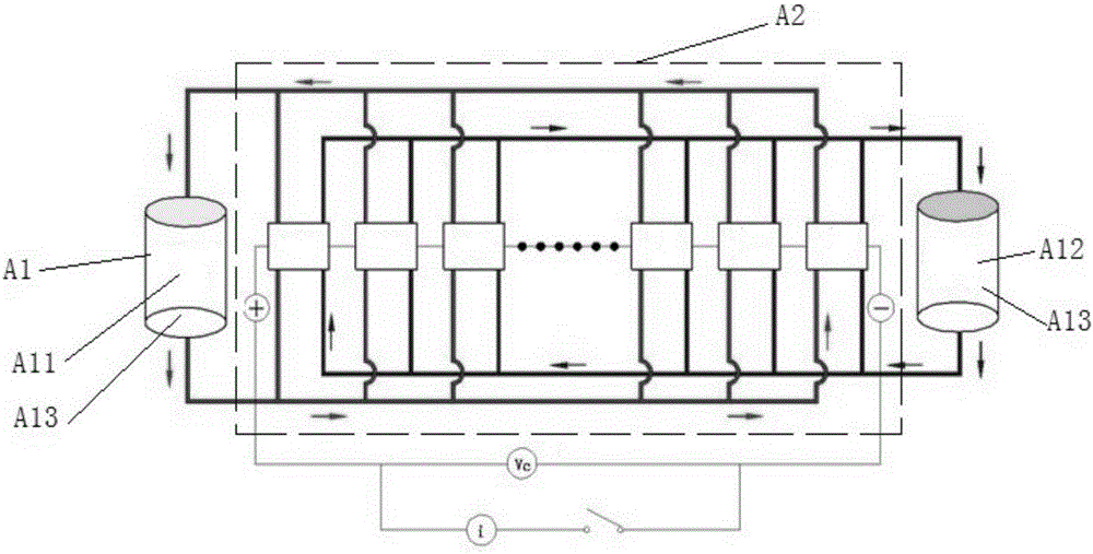
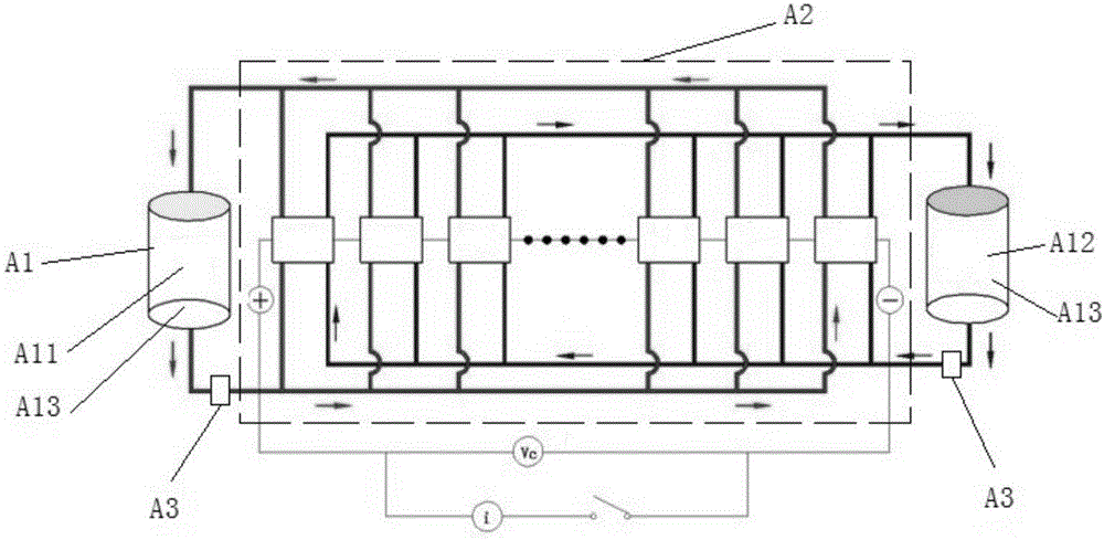
[0064] A liquid flow battery, its structural schematic diagram is shown in image 3 , specifically: including a power supply group A1 providing power for the circuit, a stack group A2 and a branch circuit arranged in series in the circuit;

[0065] The power pack A1 includes a positive electrode liquid tank A11 for storing electrolyte and a negative electrode liquid tank A12 for storing electrolyte, and the output ends of the positive electrode liquid tank A11 and the negative electrode liquid tank A12 are both provided with an electric pump A13, which is located at the On the outlet pipeline of the electric pump A13 at the output end of the positive electrode liquid tank A11 and on the outlet pipeline of the electric pump A13 at the output end of the negative electrode liquid tank A12, at least one flow battery current interrupter A3 is provided. (That is, the outlet pipelines of the two electric pumps A13 are provided with flow battery current interrupters A3, and the number...

Embodiment 2

[0072] A liquid flow battery, which is different from Embodiment 1 only in that the current interrupter for the liquid flow battery is different, see Figure 6 and Figure 7 , the details are as follows: the blade part 4.3 includes three sets of blade pieces 4.31 arranged side by side up and down, the blade piece 4.31 includes a group of blades B arranged in a spiral manner, and the blade B at the bottom includes the Tail structure A.

[0073]The working principle of the current interrupter for the flow battery of this embodiment is different from that of Embodiment 1 in that: the electrolyte flowing into the cylindrical barrel 4.1 through the liquid inlet 1.12 falls to the uppermost blade B, driving the The top blade B rotates; then it falls into the blade B on the next layer and drives it to rotate. According to this principle, the electrolyte falls on the bottom blade B and drives it to rotate. When the tail structure A overlaps with the liquid discharge port 1.22, the li...

Embodiment 3

[0076] A liquid flow battery, which is different from Embodiment 1 only in that the current interrupter for the liquid flow battery is different, see Figure 8 , the details are as follows: the electrolyte inlet pipe 2 communicates with the first cylinder 1.11 through a connecting pipe 5, and the connecting pipe 5 includes a conduit 5.1 arranged inside the rotating column 4.2 and a tube located in the first cylinder 1.11 Connection joint 5.2 in communication with said conduit 5.1.

[0077] The connection joint 5.2 is a hemispherical structure, and a plurality of through holes 5.21 are arranged on it, and the central axes of the plurality of through holes 5.21 are radially arranged.

[0078] The working principle of the current interrupter for the flow battery is different from that of Embodiment 1 only in that: the electrolyte enters the inflow guide after passing through the conduit 5.1 arranged in the rotating column 4.2 and the connecting joint 5.2 arranged at the end of th...


PUM


Abstract

The invention discloses current cutouts used by a flow battery. Each current cutout comprises a shell, an electrolyte inlet pipe, an electrolyte outlet pipe and a current cutoff part, wherein the electrolyte inlet pipe provides a channel for electrolyte to flow into the shell; the electrolyte outlet pipe provides a channel for the electrolyte to flow out of the shell; the current cutoff part is used for intermittently outputting the electrolyte flowing into the shell in a rotary manner. The current cutouts used by the flow battery have the beneficial effects that the integral structure is concise; the current cutoff parts enable the liquid flow to intermittently flow in a rotary manner, so that the electrolyte in electrolyte pipelines is intermittently disconnected, thus being capable of eliminating the shunt leakage current. The invention also discloses the flow battery. By additionally arranging the current cutouts used by the flow battery on outlet pipelines of electric pumps, closed circuits can be disconnected to intermittently input the electrolyte to each electric pile section by section and the electrolyte in the electrolyte pipelines is intermittently disconnected, so that the shunt current caused because the flow battery shares the electrolyte can be prevented.

Description

technical field [0001] The invention relates to the technical field of batteries, in particular to a current breaker for a flow battery and a flow battery using the current breaker. Background technique [0002] The principle of the all-vanadium redox flow battery is: use the flowing vanadium electrolyte aqueous solution as the energy storage medium, convert the electrical energy into chemical energy and store it in the vanadium ion pairs of different valence states, and convert the chemical energy into electrical energy output when needed. It has technical characteristics such as large capacity, long life, low cost, high efficiency, safety and reliability, and is expected to play an important role in the field of large-scale energy storage. [0003] Generally speaking, large-scale energy storage flow batteries often contain dozens of stacks. In order to provide electrolyte for each stack, the electrolyte is generally transported and distributed through public flow channels ...

Claims


Application Information

Patent Timeline
IPC IPC(8): H01M8/18H01M8/0258H01M8/04119
CPCH01M8/02H01M8/04201H01M8/188Y02E60/50
Inventor 余辰光童禄萍胡永清吴雄伟
Owner 江西银汇新能源有限公司
Why Eureka
Try Eureka