Defected ground decoupling structure used for microstrip array antenna

A microstrip array, defect ground technology, applied in the direction of antenna grounding switch structure connection, antenna coupling, antenna grounding device, etc., can solve the problem of increasing the equivalent capacitance and equivalent inductance of the microstrip transmission line, high design and manufacturing costs, and complex structure. and other problems, to achieve the effect of saving optimization time, high isolation, and good radiation characteristics

Active Publication Date: 2016-12-07
HARBIN ENG UNIV
View PDF3 Cites 18 Cited by
  • Summary
  • Abstract
  • Description
  • Claims
  • Application Information

AI Technical Summary

Problems solved by technology

But there is no doubt that the above two electromagnetic bandgap and metamaterial units have more complex structures, which have high design and manufacturing costs
The defective ground structure has a very good effect on decoupling. The defective ground structure...

Method used


Image

  • Defected ground decoupling structure used for microstrip array antenna
  • Defected ground decoupling structure used for microstrip array antenna
  • Defected ground decoupling structure used for microstrip array antenna

Examples


Embodiment 1

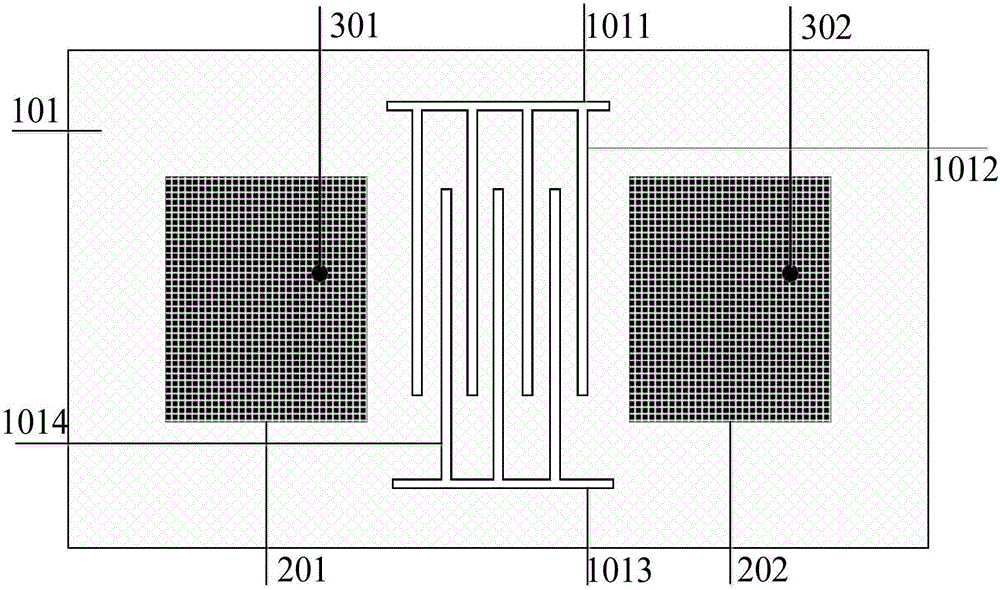
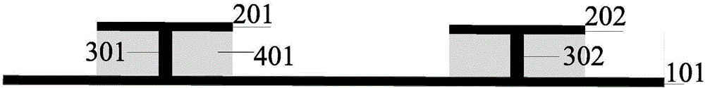
[0014] Example 1: Combining Figure 1 to Figure 3 , the present invention includes a common ground plate 101 formed on the lower surface of the dielectric substrate, rectangular radiation patches 201 and 202 on the upper surface, two coaxial feeds 301 and 302, and a groove structure is provided on the common ground plate 101, and the groove structure includes The upper comb handle unit 1011, the upper four comb tooth units 1012, the lower comb handle unit 1013 and the lower comb tooth unit 1014, and each unit is etched on the common ground plate to reduce the coupling between the microstrip antenna arrays, and at the same time Improve isolation. The comb teeth of the upper comb unit 1012 and the comb teeth of the lower comb unit 1014 cross each other to form a cross decoupling structure. The rectangular radiating patches 201 and 202 correspond to the centerline of the rectangular dielectric substrate symmetrical to the dielectric substrate. The two coaxial feeders 301 and 30...

Embodiment 2

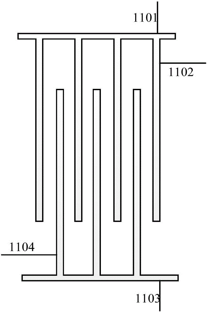
[0015] Embodiment 2: Based on the above embodiment, the distance between the comb teeth of the comb unit of the present invention is equal. According to the defect-related theory, the unit structure is designed to reduce coupling and improve isolation. The upper and lower cross radiation is adopted, and the distance between the comb teeth is equal. The upper and lower comb handle units are symmetrical about the center of the antenna, which is convenient for design and manufacture. The specific dimensions are: the length and width of the comb teeth of the upper comb handle unit 1101 can be designed according to its decoupling frequency, and the length and width of the comb teeth of the upper comb handle unit 1102 cooperate with the upper comb handle unit to achieve the purpose of decoupling , the length and width of the comb teeth and the distance between the upper and lower comb teeth can be adjusted to meet the required requirements, and the distance between the structure of t...

Embodiment 3

[0016] Embodiment 3: Based on the above embodiment, further, the dielectric substrate 401 of the present invention is an FR4 dielectric with a dielectric constant of 4.4, in order to reduce the design cost, and the size of the dielectric substrate is designed using miniaturization technology, that is, the length of the dielectric substrate 401 and width are designed according to the principle of miniaturized microstrip antenna. The metal ground plate 101 under the dielectric substrate is made of copper. The rectangular radiation patches 201 and 202 on the upper surface of the dielectric substrate are made of copper material.

[0017] A microstrip array antenna based on defect ground decoupling of the present invention uses a defect ground to realize decoupling, and as long as an appropriate size is selected, the coupling between antennas can be greatly reduced and the isolation degree can be improved at the same time. Such as Figure 4 As shown, a kind of microstrip array an...


PUM


Abstract

The invention provides a defected ground decoupling structure used for a microstrip array antenna. Two microstrip array antenna array elements are arranged on a common grounding plate, wherein a groove structure is designed on the common grounding plate between the two microstrip array antenna array elements; each microstrip array antenna array element comprises a dielectric substrate and a rectangular radiation patch and a coaxial feed element which are arranged on the upper surface of the dielectric substrate; the coaxial feed element of each microstrip array antenna array element is connected with the corresponding rectangular radiation patch and an SMA inner conductor concurrently; the SMA inner conductor is connected with the common grounding plate; the groove structure comprises two comb-shaped defected ground structures which are arranged oppositely in a crossed manner; each comb-shaped defected ground structure comprises a comb handle unit and comb teeth units; and the difference between the number of the comb teeth in the first group of comb teeth units and the number of the comb teeth in the second group of comb teeth units is 1. By adoption of the defected ground decoupling structure, the coupling energy between antennas is absorbed; in addition, the isolation degree between the array antennas is improved, thereby satisfying the requirements of the antennas; and in addition, the defected ground decoupling structure has the advantages of simple design and convenient processing.

Description

technical field [0001] The present invention relates to a decoupling structure, in particular to a defect decoupling structure for a microstrip array antenna. Background technique [0002] Array antennas are widely used in the field of radio communication due to their high gain and strong directivity. With the improvement of equipment integration, the miniaturization of array antennas has also been rapidly developed. However, the research on array antennas has always been restricted by bottlenecks such as mutual coupling between array elements. The generation of surface currents between antenna elements greatly increases the degree of coupling and seriously deteriorates the characteristics of array antennas. Therefore, how to arrange multiple antennas in a miniaturized mobile terminal device and realize the independent work of each antenna and the independent performance become the key to the research of array antennas. It can be seen that the research on the high isolation...

Claims


Application Information

Patent Timeline
IPC IPC(8): H01Q1/52H01Q1/50H01Q1/48H01Q1/38H01Q21/00
Inventor 李迎松于凯王燕燕
Owner HARBIN ENG UNIV
Why Eureka
Try Eureka