A Defective Ground Decoupling Structure for Microstrip Array Antenna
A technology of microstrip array and defective ground, which is applied in the direction of antenna grounding switch structure connection, antenna coupling, antenna grounding device, etc., can solve high design and manufacturing costs, increase equivalent capacitance and equivalent inductance of microstrip transmission line, complex structure and other issues to achieve high isolation, save optimization time, and good radiation characteristics
- Summary
- Abstract
- Description
- Claims
- Application Information
AI Technical Summary
Problems solved by technology
Method used
Image
Examples
Embodiment 1
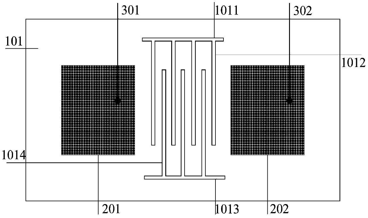
[0014] Example 1: Combining Figure 1 to Figure 3 , the present invention includes a common ground plate 101 formed on the lower surface of the dielectric substrate, rectangular radiation patches 201 and 202 on the upper surface, two coaxial feeds 301 and 302, and a groove structure is provided on the common ground plate 101, and the groove structure includes The upper comb handle unit 1011, the upper four comb tooth units 1012, the lower comb handle unit 1013 and the lower comb tooth unit 1014, and each unit is etched on the common ground plate to reduce the coupling between the microstrip antenna arrays, and at the same time Improve isolation. The comb teeth of the upper comb unit 1012 and the comb teeth of the lower comb unit 1014 cross each other to form a cross decoupling structure. The rectangular radiating patches 201 and 202 correspond to the centerline of the rectangular dielectric substrate symmetrical to the dielectric substrate. The two coaxial feeders 301 and 30...
Embodiment 2
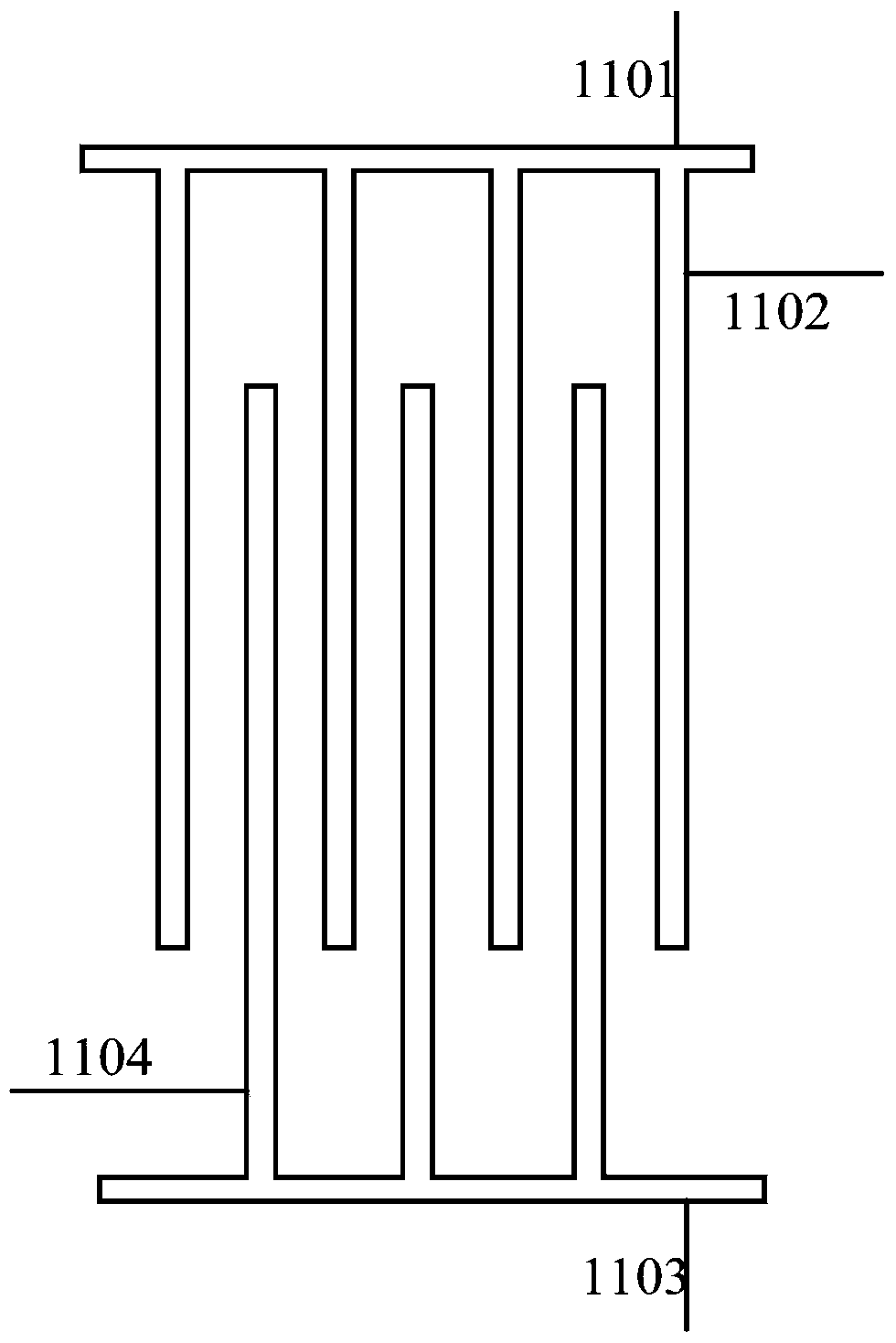
[0015] Embodiment 2: Based on the above embodiment, the distance between the comb teeth of the comb unit of the present invention is equal. According to the defect-related theory, the unit structure is designed to reduce coupling and improve isolation. The upper and lower cross radiation is adopted, and the distance between the comb teeth is equal. The upper and lower comb handle units are symmetrical about the center of the antenna, which is convenient for design and manufacture. The specific dimensions are: the length and width of the comb teeth of the upper comb handle unit 1101 can be designed according to its decoupling frequency, and the length and width of the comb teeth of the upper comb handle unit 1102 cooperate with the upper comb handle unit to achieve the purpose of decoupling , the length and width of the comb teeth and the distance between the upper and lower comb teeth can be adjusted to meet the required requirements, and the distance between the structure of t...
Embodiment 3
[0016] Embodiment 3: Based on the above embodiment, further, the dielectric substrate 401 of the present invention is an FR4 dielectric with a dielectric constant of 4.4, in order to reduce the design cost, and the size of the dielectric substrate is designed using miniaturization technology, that is, the length of the dielectric substrate 401 and width are designed according to the principle of miniaturized microstrip antenna. The metal ground plate 101 under the dielectric substrate is made of copper. The rectangular radiation patches 201 and 202 on the upper surface of the dielectric substrate are made of copper material.
[0017] A microstrip array antenna based on defect ground decoupling of the present invention uses a defect ground to realize decoupling, and as long as an appropriate size is selected, the coupling between antennas can be greatly reduced and the isolation degree can be improved at the same time. Such as Figure 4 As shown, a kind of microstrip array an...
PUM
 Abstract
Description
Claims
Application Information
 - R&D
- Intellectual Property
- Life Sciences
- Materials
- Tech Scout
- Unparalleled Data Quality
- Higher Quality Content
- 60% Fewer Hallucinations
Browse by: Latest US Patents, China's latest patents, Technical Efficacy Thesaurus, Application Domain, Technology Topic, Popular Technical Reports.
© 2025 PatSnap. All rights reserved.Legal|Privacy policy|Modern Slavery Act Transparency Statement|Sitemap|About US| Contact US: help@patsnap.com


