Ocean pile driving barge
A piling ship and marine technology, applied in the field of ships, can solve the problems of difficult to meet the rapid growth of coastal infrastructure construction projects, do not meet the requirements of energy conservation and environmental protection, and the overall technical level is not high, so as to improve environmental protection and operating economy, The effect of optimizing the configuration of electromechanical equipment and expanding the scope of application
- Summary
- Abstract
- Description
- Claims
- Application Information
AI Technical Summary
Problems solved by technology
Method used
Image

Examples
Embodiment Construction
[0045] In order to better understand the present invention, the present invention is described in detail below in conjunction with specific examples. It will, however, be evident that various changes and modifications can be made to the present invention without departing from the broader spirit and scope of the invention as defined in the appended claims. Therefore, the following examples have an illustrative rather than a limiting meaning.
[0046] Example:
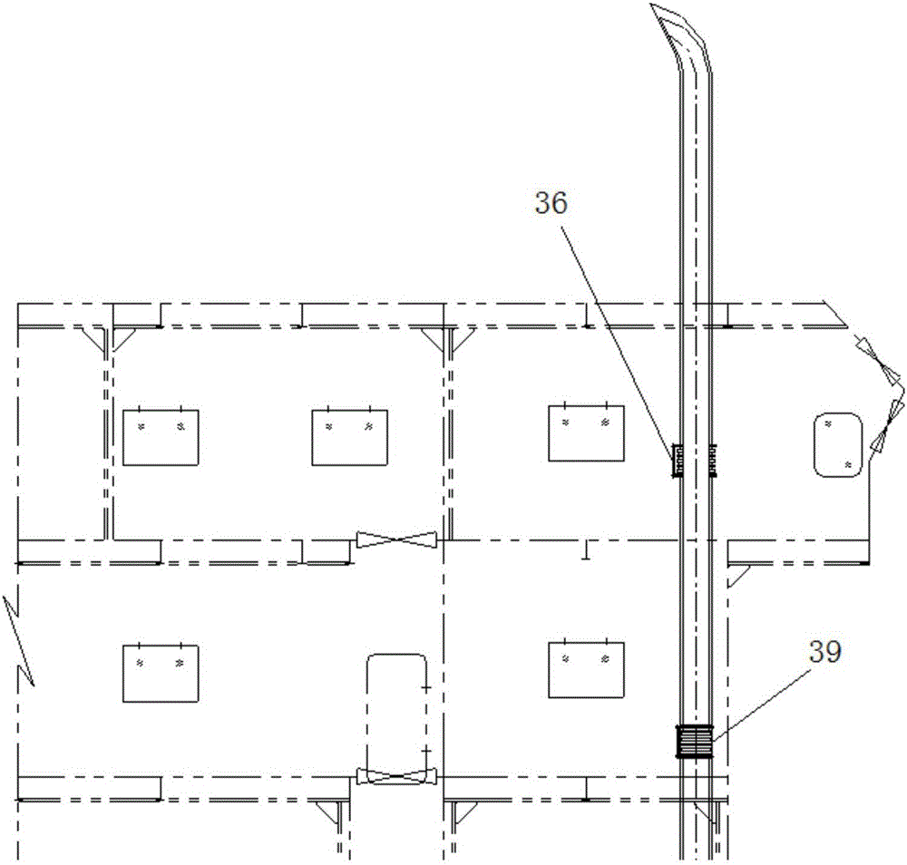
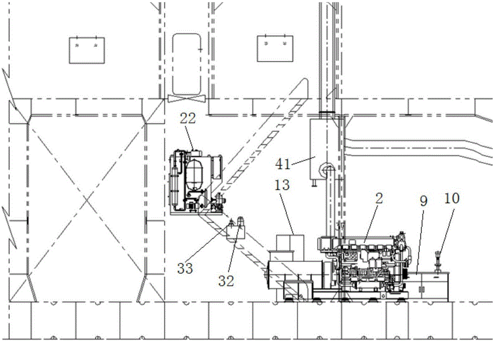
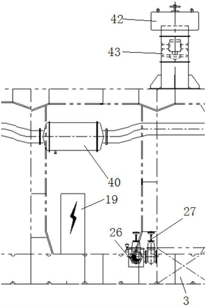
[0047] A marine piling vessel such as Figure 1 to Figure 27 As shown, including the hull and the pile frame, the hull is provided with a first oil pump diesel engine 1, an auxiliary generator set 2, a seawater tank 3, a second oil pump diesel engine 4, an output oil pump transfer gearbox 5, a sewage oil hand pump 6, a portable Type air foam gun 7, oil and sewage separation device 8, workbench 9, bench drill 10, vise 11, grinder 12, tool box 13, miscellaneous air bottle 14, air compressor 15, third oil pump diesel eng...
PUM
 Abstract
Description
Claims
Application Information
PatSnap Eureka turns technology decisions into work you can execute. Powered by our Innovation Knowledge Graph, it runs expert workflows across engineering, life sciences, materials and intellectual property. Get your review-ready output in minutes.


