
Robot special for wave compensation and wave compensation method

A technology of wave compensation and robotics, which is applied in the directions of manipulators, program-controlled manipulators, and equipment for increasing the stability of ships. It can solve the problems of disjoint wrist rotation axes, small movement space, and large overall weight, so as to increase the working space and flexibility. Accurate, achieve overall position adjustment, simple and compact structure

Inactive Publication Date: 2016-12-21
JIANGSU UNIV OF SCI & TECH
View PDF8 Cites 18 Cited by
  • Summary
  • Abstract
  • Description
  • Claims
  • Application Information

AI Technical Summary

Problems solved by technology

For example, the Amplemann motion compensation gangway system on the ship is a wave compensation system based on the Steward platform. It uses hydraulic and pneumatic devices to achieve compensation, but the space required for installation and its own mass are large, the movement space is small, and the operating range is limited. Small and cannot fit in a corrosion-resistant hull or hull due to size
At the same time, the base of the traditional tandem robot is fixed, and the maximum working range is limited.
The traditional tandem robot wrist has a complex structure and a large overall weight, and the weight of the latter degree of freedom mechanism becomes the load of the former degree of freedom mechanism, and it is easy to cause the rotation axes of the wrist to disjoint or produce offset distances, which brings difficulties to the robot wrist control and low integration

Method used


Image

  • Robot special for wave compensation and wave compensation method
  • Robot special for wave compensation and wave compensation method
  • Robot special for wave compensation and wave compensation method

Examples


Embodiment Construction

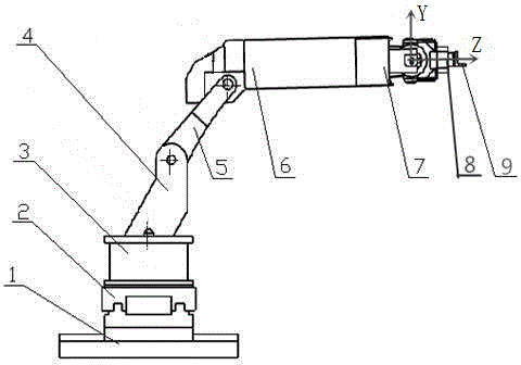
[0023] see figure 1 The bottom of the special robot for wave compensation shown is the adjustment guide rail. The adjustment guide rail is composed of the longitudinal guide rail combination 1 and the horizontal guide rail combination 2. The lower part is the longitudinal guide rail combination 1, and the upper part is the horizontal guide rail 2. The adjustment guide rail passes through the lower longitudinal guide rail combination 1. The bolts are fastened to the deck of the ship. The upper end of the adjustment guide rail is a mechanical arm, and the mechanical arm is mainly composed of a mechanical arm base 3, a large arm 4, a connecting arm 5, and a small arm 6. The mechanical arm base 3 is fixed on the adjustment guide rail by bolts, so that the whole mechanical arm is connected to the adjustment guide rail through the mechanical arm base 3 . A position sensor is installed at the center of the base 3 of the manipulator to detect the roll, pitch and heave of the robot as...


PUM


Abstract

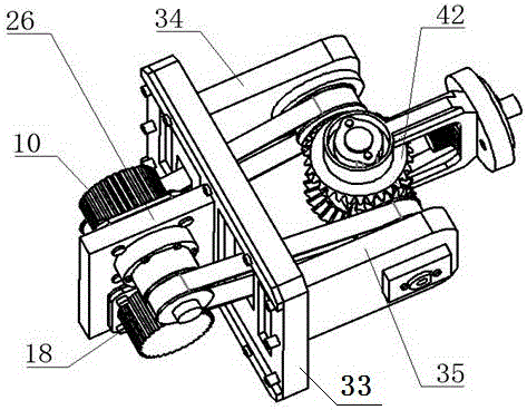
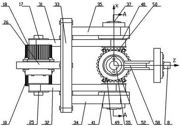
The invention discloses a special robot with a wave compensation function and a wave compensation method, and belongs to the field of offshore ship operation. The front end of a small arm is connected with the rear end of a wrist mechanism, the front end of the wrist mechanism is rigidly connected with an end effector actuator, the rear end of the wrist mechanism comprises a first actuator and a second actuator, the front end of the wrist mechanism comprises a differential mechanism and two supporting arms, and a supporting frame is arranged in the middle of the wrist mechanism and fixedly connected with the front end of the small arm. The left supporting arm and the right supporting arm are fixedly connected to the front lateral sides of the supporting frame, and the differential mechanism is arranged between the two supporting arms. The differential mechanism is composed of four bevel gears, a deflection shaft and two pitching driving shafts, wherein the deflection shaft is vertically arranged, the central line of the first pitching driving shaft and the central line of the second pitching driving shaft are collinear and perpendicular to the central line of the deflection shaft, and the two pitching driving shafts are symmetrically arranged at the left side and the right side of the deflection shaft. The wrist mechanism has three independent freedom degrees so that the robot can have more postures, and rolling, pitching and yawing, caused by wind waves, of a ship can be compensated in real time.

Description

technical field [0001] The invention relates to the technical field of offshore ship operations, in particular to a special-purpose robot with a wave compensation function. Background technique [0002] The activities of ships on the ocean are different from those on land. Ships will fluctuate irregularly with the waves, resulting in changes in their relative positions. How to isolate the disturbance is to compensate for the fluctuations caused by waves, so as to ensure the stability and safety of ocean operations. Activities in the ocean range are of great significance. [0003] At present, the application of wave compensation robots is mainly concentrated in drilling operations on offshore platforms, offshore cargo lifting, offshore wind power generation, submersible recovery and lifting, and material transfer between ships. Most of the wave compensating robots adopt the form of parallel platform, which has the advantages of high rigidity, strong bearing capacity, high pr...

Claims


Application Information

Patent Timeline
IPC IPC(8): B63B39/00B25J11/00B25J9/08
CPCB63B39/00B25J9/08B25J11/00
Inventor 卢道华陈文君胡可丽王佳
Owner JIANGSU UNIV OF SCI & TECH
Learn More