Material issuing tank utilizing pressure-conveying type high-pressure dense-phase multi-path pneumatic conveying mode and conveying system of material issuing tank

A pneumatic conveying system, a technology of pneumatic conveying, is used in conveying bulk materials, conveyors, transportation and packaging, etc. It can solve problems such as mutual interference, uneven flow, overall flow or single-channel flow is not smooth, and achieve simplified structure, The effect of reducing the difficulty of rolling and ensuring safety

Active Publication Date: 2016-12-21
SOUTHEAST UNIV
View PDF9 Cites 1 Cited by
  • Summary
  • Abstract
  • Description
  • Claims
  • Application Information

AI Technical Summary

Problems solved by technology

[0004] Purpose of the invention: Aiming at the above-mentioned prior art, a pressure-feeding high-pressure dense-phase multi-channel pneumatic conveying delivery tank and its delivery system are proposed to solve the problems caused by the single delivery tank adopting multi-channel bottom discharge pressure-feeding conveying. The overall flow of powder in the material tank or the flow of single channel is not smooth and uneven, and the problem of mutual interference and synergy between the overall flow of powder in the material tank and the single channel flow

Method used


Image

  • Material issuing tank utilizing pressure-conveying type high-pressure dense-phase multi-path pneumatic conveying mode and conveying system of material issuing tank
  • Material issuing tank utilizing pressure-conveying type high-pressure dense-phase multi-path pneumatic conveying mode and conveying system of material issuing tank
  • Material issuing tank utilizing pressure-conveying type high-pressure dense-phase multi-path pneumatic conveying mode and conveying system of material issuing tank

Examples


Embodiment Construction

[0021] The present invention will be further explained below in conjunction with the accompanying drawings.

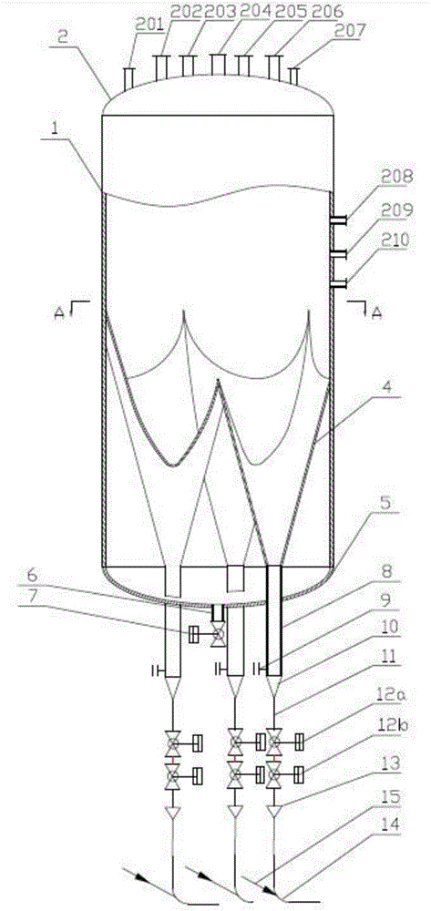
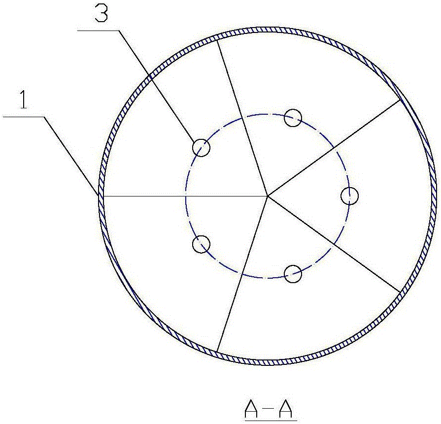
[0022] Such as figure 1 As shown, a pressure-feeding high-pressure dense-phase five-way pneumatic conveying tank includes an outer cylinder body 1 and five cone buckets 4, and the angle between the busbars of each cone bucket 4 is 10° to 30°. All cone buckets 4 are vertically arranged inside the outer cylinder 1 and evenly distributed along the circumference of the outer cylinder 1. The maximum horizontal section of each cone 4 is located on the same horizontal plane, and the vertical distance from the center point of the circular outlet 3 at the bottom of each cone to the inner wall of the outer cylinder 1 is a quarter of the inner diameter of the outer cylinder, such as figure 2 shown. All cone buckets are connected by smooth intersecting lines to form a multi-cone bucket interconnection. An intersection point of the circumference of the largest horizontal section...


PUM


Abstract

The invention discloses a material issuing tank utilizing a pressure-conveying type high-pressure dense-phase multi-path pneumatic conveying mode and a conveying system of the material issuing tank. A plurality of conical hoppers are arranged inside the material issuing tank, so that natural and smooth transition as well as a non-blind-area connection design is realized between single conical hopper inside the material issuing tank and an outer barrel body as well as between the conical hoppers, and therefore, powder in the material issuing tank is guaranteed to integrally flow downwards freely, powder stacking and holding-up phenomena in the material issuing tank are prevented, and mutual interference and series-flow phenomena of gas and powder among the plurality of the conical hoppers are prevented. The system can realize multi-path stable conveying with same conveying capacity, under high pressure, of ultrahigh dense-phase powder via single material issuing tank, and realize conveying maximal amount of powder with minimal amount of a conveying medium, so that the defects that blockage is easily caused, blockage is difficult to eliminate, and conveying amount for materials in each conveying pipeline is unstable in a charging and discharging mode of a fluidization tank are avoided; and meanwhile, the material issuing tank has relatively good regulating performance on powder conveying flow, improves reliability and controllability of equipment operation, and reduces number of devices of the conveying system.

Description

technical field [0001] The invention relates to a delivery tank and its conveying system for powder material supply of ultra-dense phase, high stability and large conveying capacity by using pressure-feeding multi-channel high-pressure dense-phase pneumatic conveying, which is especially suitable for dry coal powder processing. Hydrogen coal gasification, IGCC power generation, chemical, metallurgical flying, and other processing industries for powder material transportation. Background technique [0002] In recent decades, with the development of dry coal powder pressurized gasification and hydrogenation gasification, and IGCC technology, in order to reduce the investment cost, floor area and system complexity of the transportation system, the single-tank multi-channel high-pressure dense-phase pneumatic conveying technology received more and more attention. [0003] At present, the pulverized coal feeding technology used in the high-pressure dry pulverized coal gasificati...

Claims


Application Information

Patent Timeline
IPC IPC(8): B65G53/36B65G53/16B65G53/40
CPCB65G53/16B65G53/36B65G53/40
Inventor 熊源泉沈湘林周海军
Owner SOUTHEAST UNIV
Why Eureka
Try Eureka