Internal combustion engine exhaust gas utilization heat energy power system based on working medium cyclic condensation

A technology of working medium circulation and power system, which is applied in the direction of machines/engines, mechanical equipment, steam engine devices, etc., can solve the problems of high exhaust port pressure, small external waste heat absorption rate, and small output power of thermal energy generators, etc., to achieve reduction Effects of heat energy waste and cooling energy consumption, improvement of gasification efficiency and condensation efficiency, stabilization of gasification temperature and working medium flow rate

Inactive Publication Date: 2016-12-21
郭远军
View PDF0 Cites 0 Cited by
  • Summary
  • Abstract
  • Description
  • Claims
  • Application Information

AI Technical Summary

Problems solved by technology

[0007] However, the common problems of existing thermal power generation equipment are: a. The temperature at the exhaust port of the turbine is relatively high, resulting in high pressure at the exhaust port, and the work conversion efficiency of the turbine is low; b. The heat displacement of the condensing device is relatively large , the waste of heat energy is large, the condensation speed through natural condensation is slow, and the active condensation method (fan air cooling or liquid pump water cooling) requires additional power consumption; c. The temperature requirements for high-temperature heat sources are high, generally above 200 ° C, and The thermal energy conversion efficiency is low, and the thermal energy conversion efficiency is generally 15% to 35%; d. Gasification heat absorption is slow, and the output power of the thermal energy machine is relatively small; e. The heat collection effect of the heat collection device is not good, and the external waste heat absorption rate is small , f. The gasification temperature of the working fluid is unstable, the condensation effect of the working fluid is not good, and the working fluid is easy to deteriorate or appear impurities
[0008] On the other hand, the thermal energy conversion efficiency of the existing internal combustion engine is about 45%, and the exhaust temperature of the internal combustion engine exhaust gas can be as high as 400°C, and there is a large energy waste in the exhaust emission.

Method used


Image

  • Internal combustion engine exhaust gas utilization heat energy power system based on working medium cyclic condensation
  • Internal combustion engine exhaust gas utilization heat energy power system based on working medium cyclic condensation
  • Internal combustion engine exhaust gas utilization heat energy power system based on working medium cyclic condensation

Examples


Embodiment 1

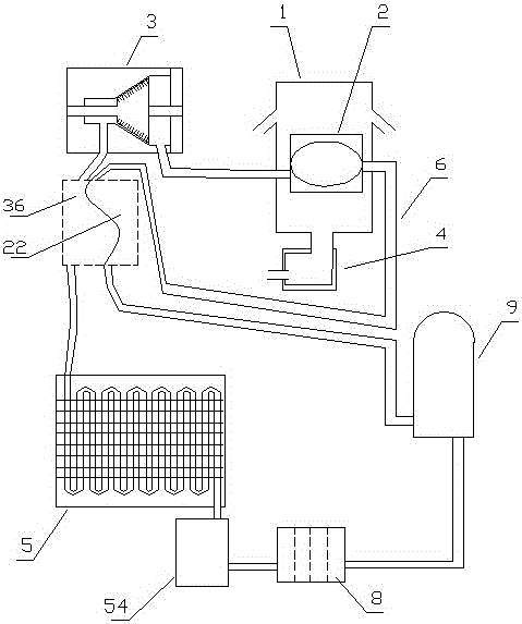
[0082] Embodiment one (such as figure 1 Shown): A power system for utilizing heat energy of internal combustion engine exhaust gas based on working medium circulation condensation, including heat collector 1, gasification device 2, turbine 3, internal combustion engine exhaust pipe 4, condensing device 5, circulation pipeline 6, and circulating working medium 7 And the one-way hydraulic pump 9, the gasification device 2, the turbine 3, the condensing device 5 and the one-way hydraulic pump 9 realize the circulation communication through the circulation pipeline 6 in sequence. Outside the gasification device 2, it is used for gasification heating of the working fluid in the gasification device 2;

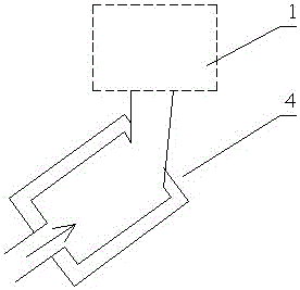
[0083] (Such as figure 2 As shown) the exhaust pipe 4 of the internal combustion engine is connected to the heat collector 1;

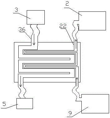
[0084] (Such as image 3 As shown) the gasification device 2 includes a gasification chamber 21 and a preheating chamber tube 22, the preheating chamber...

Embodiment 2

[0096] Embodiment two (such as Image 6 Shown): The difference from Embodiment 1 is that the heat collecting device 1 includes an upper cover 11 and a lower cover 12, a heating port 13 is provided in the middle of the lower cover 12, and the upper cover 11 and the lower cover 12 are respectively located on the upper and lower sides. Between 11 and the lower cover 12 is a heat collecting chamber 14, two layers of upper cover protruding rings 111 are distributed on the lower part of the upper cover 11 of the heat collecting device 1, and two layers of lower cover protruding rings 121 are distributed on the upper part of the lower cover 12 of the heat collecting device 1, The protruding ring 111 of the upper cover and the protruding ring 121 of the lower cover are staggered.

[0097] By carrying out experiments on the internal combustion engine tail gas utilization heat energy power system based on working medium circulation condensation in the above-mentioned embodiment two, th...

Embodiment 3

[0098] Embodiment three (such as Figure 7 Shown): The difference from Embodiment 1 is that the lower part of the upper cover 11 of the heat collecting device 1 is provided with a three-layer upper cover protruding ring 111, and the upper part of the lower cover 12 of the heat collecting device 1 is distributed with a three-layer lower cover protruding ring 121 , the upper cover protruding ring 111 and the lower cover protruding ring 121 are staggered.

[0099] By carrying out experiments on the internal combustion engine tail gas utilization heat energy power system based on working medium circulation condensation in the above-mentioned embodiment three, the exhaust gas of different temperatures is discharged into the heat collector 1, the exhaust gas displacement is 1.5L / s, and the working medium flow rate in the circulation pipe is according to The exhaust gas of the internal combustion engine based on the circulation and condensation of the working fluid is adjusted by th...


PUM


Abstract

The invention discloses an internal combustion engine exhaust gas utilization heat energy power system based on working medium cyclic condensation. The internal combustion engine exhaust gas utilization heat energy power system comprises a gasification device, a turbine, a condensation device and a unidirectional hydraulic pump which cyclically communicate with one another in sequence through a circulating pipeline, wherein a circulating working medium is accommodated in the circulating pipeline; the heat collection device is mounted outside the gasification device, and communicates with an internal combustion engine exhaust gas pipe; the gasification device comprises a gasification cavity and a preheating cavity pipe; a pre-condensation cavity is arranged at an exhaust opening of the turbine; and the preheating cavity pipe and the pre-condensation cavity are in contact in parallel. The internal combustion engine exhaust gas utilization heat energy power system based on working medium cyclic condensation can accelerate condensation, improve the efficiency of the turbine and reduce the discharging amount of heat energy, so that the heat energy conversion efficiency can be improved.

Description

technical field [0001] The invention belongs to the field of energy utilization equipment, in particular to a heat energy power system utilizing exhaust gas of an internal combustion engine based on circulating condensation of working fluid. Background technique [0002] Energy is an important material basis for the survival and development of human society. Throughout the history of the development of human society, every major progress of human civilization is accompanied by the improvement and replacement of energy. The development and utilization of energy has greatly promoted the development of the world economy and human society. [0003] However, with the continuous development and consumption of energy, non-renewable energy sources such as petroleum, coal mines, and natural gas are gradually reduced, and energy conservation and recycling are gradually being valued. The basic content of my country's current energy strategy is: adhere to the priority of conservation,...

Claims


Application Information

Patent Timeline
Patent Type & Authority Applications(China)
IPC IPC(8): F01K11/02F01K27/02
CPCF01K11/02F01K27/02
Inventor 郭远军
Owner 郭远军
Why Eureka
Try Eureka