Charing and gasification composite furnace

A technology of carbonization and gas, which is applied in the direction of gasification process, gasification catalyst, gasification device feeding tool, etc., can solve the problems of difficulty, high efficiency and reasonable utilization, and achieve the goal of avoiding the leaching of heavy metals, increasing the moisture content, and avoiding dust. Effect

Active Publication Date: 2016-12-28
TONGJI UNIV
View PDF4 Cites 4 Cited by
  • Summary
  • Abstract
  • Description
  • Claims
  • Application Information

AI Technical Summary

Problems solved by technology

[0004] In view of the fact that the existing technology is difficult to efficiently and rationally utilize urban waste, sludge, sawdust, broken bark, rice husk, rice straw, peanut shell, peanut v...

Method used


Image

  • Charing and gasification composite furnace
  • Charing and gasification composite furnace
  • Charing and gasification composite furnace

Examples


Embodiment 1

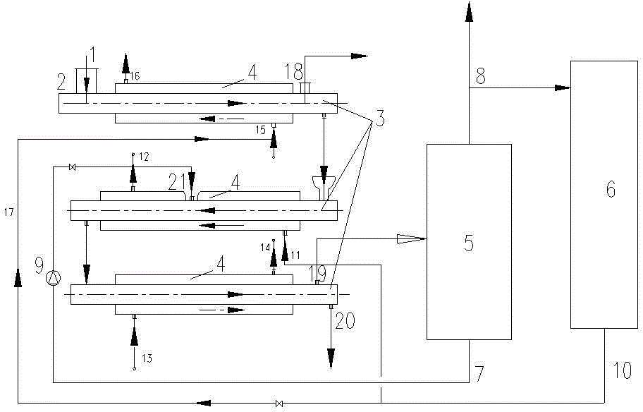
[0033] Such as figure 1 As shown, the carbonization and gasification compound furnace includes three stages of pyrolysis channels 3 , flue gas channels 4 , oil and gas separators 5 and gas combustion furnaces 6 . The first pyrolysis channel 3 is provided with a feed port 2 and an exhaust port 18, the second pyrolysis channel 3 is provided with an oil return port 21, and the third pyrolysis channel 3 is provided with a volatile matter guide. Outlet 19 and carbon discharge port 20, each pyrolysis channel 3 forms a multi-section sleeve with the corresponding flue gas channel 4. The steam exhaust port 18 is located on the first pyrolysis channel 3 with the feed port 2, and the oil return port 21 is located in the middle and rear section of the second pyrolysis channel; the volatile matter outlet 19 It is located in front of the carbon discharge port 20 and is connected to the inlet of the oil-gas separator 5 through a pipeline; the oil cavity at the lower part of the oil-gas sep...

Embodiment 2

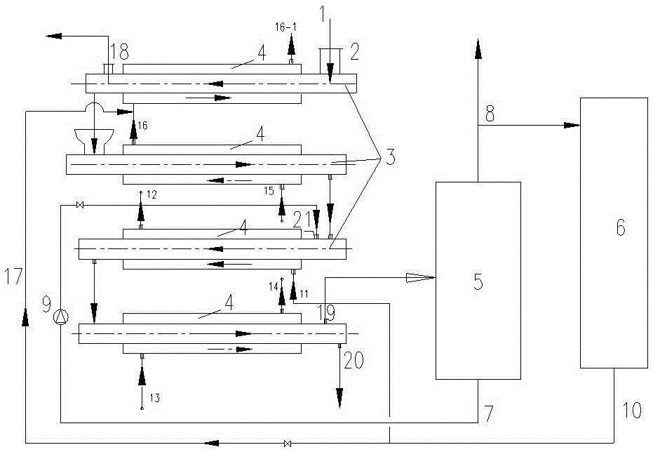
[0037] Such as figure 2 As shown, the carbonization and gasification composite furnace includes four stages of pyrolysis channels 3 , flue gas channels 4 , oil and gas separators 5 and gas combustion furnaces 6 . The pyrolysis channel 3 in the first section is provided with a feed port 2 and an exhaust port 18, the pyrolysis channel 3 in the third section is provided with an oil return port 21, and the pyrolysis channel 3 in the fourth section is provided with a volatile matter guide. Outlet 19 and carbon discharge port 20, each pyrolysis channel 3 forms a multi-section sleeve with the corresponding flue gas channel 4. The steam exhaust port 18 is located on the first-stage pyrolysis channel 3 with the feed port 2, the oil return port 21 is located on the third-stage pyrolysis channel; the volatile matter export port 19 is located on the carbon discharge channel The front of the port 20 is connected with the inlet of the oil-gas separator 5 through a pipeline; the oil cavity...

Embodiment 3

[0041] Such as figure 2 As shown, the carbonization and gasification composite furnace includes four stages of pyrolysis channels 3 , flue gas channels 4 , oil and gas separators 5 , and gas combustion furnaces 6 . The multi-stage pyrolysis channel 3 is provided with a feed port 2, a steam exhaust port 18, an oil return port 21, a volatile matter export port 19, and a carbon discharge port 20, and forms a multi-section sleeve with the flue gas channel 4. The steam exhaust port 18 is located on the pyrolysis channel 3 with the feed port 2, the oil return port 21 is located in the front section of the third stage pyrolysis channel; the volatile matter outlet 19 is located at the carbon discharge port 20 The front of the oil-gas separator 5 is connected with the inlet of the oil-gas separator 5 through a pipeline; the oil cavity at the bottom of the oil-gas separator 5 is connected to the oil return port 21 on the pyrolysis passage 3 through an oil pump 9 and a pipeline; The ai...


PUM


Abstract

The invention relates to a charing and gasification composite furnace, which can realize charing and gasification of to-be-processed materials such as garbage, sludge, sawdust, ground bark, rice husk, rice straw, peanut shell, peanut vine, coconut shell, palm shell, hemp xyloid stem, cotton stalk and straw, and two products of combustible gas and charcoal with calorific value of greater than 10-12 MJ/Nm<3> can be obtained. The charing and gasification composite furnace comprises a multistage pyrolysis channel, a flue gas channel, an oil and gas separator and a combustion gas combustion furnace. The multistage pyrolysis channel comprises a feed inlet of a to-be-processed material, a discharge port, an oil returning port, a volatile matter guiding outlet, a charcoal discharge port, and can form a segmentation sleeve with the flue gas channel; the discharge port is positioned at the pyrolysis channel with the feed inlet, the oil returning port is positioned at a middle and rear part of the pyrolysis channel; the volatile matter guiding outlet and an inlet of the oil and gas separator are connected; an oil chamber at the upper part of the oil and gas separator is connected with the oil returning port on the multistage charing pipe through an oil pump; and a gas chamber at the upper part of the oil and gas separator is simultaneously connected with a contact tube and a combustion gas combustion furnace. A connection pipe is arranged on a flue gas channel on outside of the pyrolysis channel with the oil returning port, and is connected with the combustion gas combustion furnace, and the flue gas departs from the channel, then passes through the high and low temperature material channels.

Description

technical field [0001] The invention belongs to the field of transforming waste and biomass disposal into energy and resources. Specifically, the present invention relates to a carbonization and gasification composite furnace. Background technique [0002] Including urban garbage, sludge, sawdust, shredded bark, rice husk, rice straw, peanut shell, peanut vine, coconut shell, palm shell, hemp stalk, cotton stalk, wheat straw and other raw materials are waste in most cases, but contain Abundant energy. It can be converted into heat energy by incineration; it can also be converted into combustible gas by gasification; it can also be converted into combustible gas, oil and charcoal by thermal cracking. Combustion recovers heat energy in the existing technology, but it is easy to produce secondary pollution, which usually hinders project approval; gasification technology is often difficult to implement because of the tar carried in the combustible gas, and because the calorifi...

Claims


Application Information

Patent Timeline
IPC IPC(8): C10B53/02C10J3/20C10J3/72C10C1/19C10J3/82C10J3/84
CPCC10B53/02C10C1/19C10J3/20C10J3/723C10J3/82C10J3/84C10J2200/06C10J2200/15C10J2300/0916C10J2300/0976C10J2300/0986C10J2300/1603C10J2300/1807Y02E50/10
Inventor 戴晓虎陈德珍胡雨燕尹丽洁马晓波
Owner TONGJI UNIV
Why Eureka
Try Eureka