Self-adaptive cardiac valve prosthesis

A heart valve, self-adaptive technology, applied in the field of medical devices, to achieve the effect of avoiding traction, reducing impact, and optimizing valve performance

Active Publication Date: 2017-01-04
NINGBO JENSCARE BIOTECHNOLOGY CO LTD
View PDF8 Cites 14 Cited by
  • Summary
  • Abstract
  • Description
  • Claims
  • Application Information

AI Technical Summary

Problems solved by technology

The present invention solves the problem caused by the radial expansion of the patient's own annulus in the existing anchoring technology. On the basis of ensuring the anchoring effect of the implanted valve, it can not only reduce the impact on the outflow tract after the stent is released, but also avoid damage

Method used


Image

  • Self-adaptive cardiac valve prosthesis
  • Self-adaptive cardiac valve prosthesis
  • Self-adaptive cardiac valve prosthesis

Examples


specific Embodiment 1

[0081] For a long time, whether it is Edwards or Medtronic, major valve manufacturers have adopted the expansion ratio of stent-annulus radial expansion to obtain sufficient stent anchoring force, which has been used in the field of aortic valve interventional replacement and pulmonary valve interventional replacement. It has been fully applied and has become a consensus (generally 10%-15% is the ideal circumference expansion ratio). Later, Jenavalve and Symetic applied the clamping leaflet mechanism to their products, and they still have a certain expansion ratio for the patient's valve. However, atrioventricular valves (including mitral valves and tricuspid valves) are often very difficult to accurately position and fix products due to their complex physiological structures and disease mechanisms. The current technologies for atrioventricular valve interventional replacement, such as Edwards, Medtronic and Tiara, all need to provide a certain radial expansion ratio to meet t...

specific Embodiment 2

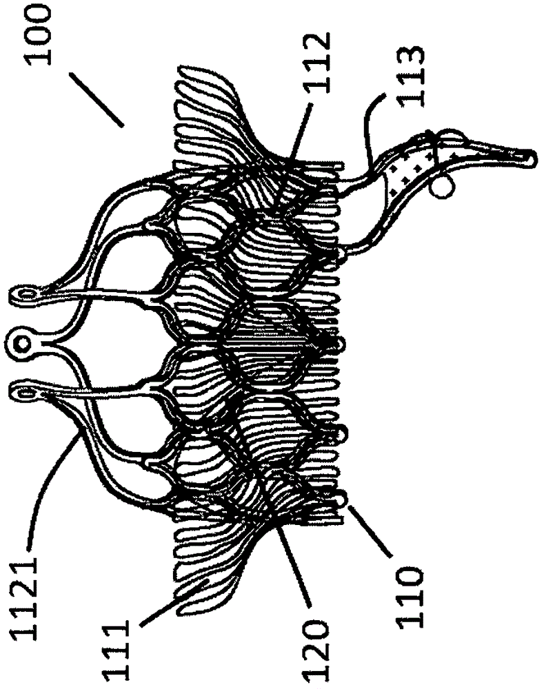
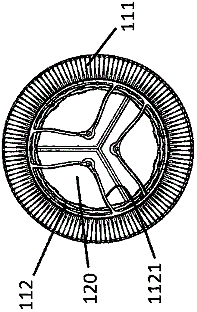
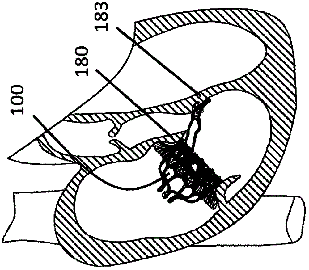
[0090] In one embodiment, as Figure 4a and Figure 4b As shown, an adaptive heart valve prosthesis 200 is used for mitral valve interventional replacement therapy, including a stent 210 and an artificial valve (not shown), and the stent 210 includes an anti-leakage ring 211 and a valve sewing segment 212, The artificial valve is fixedly connected to the valve sewing section 212, and the leak-proof ring 211 is connected to the valve sewing section 212. In a free state, the leak-proof ring 211 is located in the patient's atrium and On the patient's own valve annulus 280, the anti-leakage ring 211 can conform to the uneven contour of the atrial cavity wall or the patient's own valve annulus without restricting the systolic function of the atrium, and the valve sewing section 212 is at least partially positioned on the patient's own Between the valve leaflets, on a cross-section perpendicular to the central axis of the artificial valve, the cross-sectional area of ​​the valve se...

specific Embodiment 3

[0095] In one embodiment, as Figure 5a As shown, an adaptive heart valve prosthesis 300 is used for tricuspid valve interventional replacement therapy, including a stent 310 and an artificial valve (not shown), and the stent 310 includes an anti-leakage ring 311 and a valve sewing segment 312, The artificial valve is fixedly connected to the valve sewing section 312, the valve sewing section 312 is a cylindrical wave-shaped structure, the fixing device 313 is an inverted cone structure, and the fixing device 313 has a large diameter One end of the valve sewing section 312 is connected to the proximal end of the valve sewing section 312 by known techniques such as suture, buckle or welding, and the small diameter end of the fixing device 313 is provided with a connecting rod 315, and the connecting rod 315 is rigid. One end of the connecting rod 315 is connected to the end of the fixing device 313, the proximal part of the connecting rod 315 is provided with a fixing part 314,...


PUM


Abstract

The invention relates to a self-adaptive cardiac valve prosthesis which comprises a support and an artificial valve. The support comprises a leakproof ring and a valve sewing section which are connected, the artificial valve is fixedly connected to the valve sewing section, and at least part of the valve sewing section is located among autologous valve leaflets of a patient; on the cross section perpendicular to the central axis of the artificial valve, the cross section area of the valve sewing section is smaller than that of the autologous valve annulus of the patient, the valve sewing section cannot directly expand the autologous valve annulus of the patient in the radial direction, in a free state, the cross section area of the leakproof ring is larger than that of the autologous valve annulus of the patient, and the leakproof ring can conform to the uneven contour of the atrial chamber wall or the autologous valve annulus of the patient.

Description

[0001] Technical field: [0002] The invention belongs to the field of medical equipment, and in particular relates to an adaptive heart valve prosthesis. [0003] Background technique: [0004] The mitral valve is located at the left atrioventricular orifice and consists of five parts: the valve annulus, valve leaflets, chordae, papillary muscles, and junctional junction. Its anatomically accurate name is mitral apparatus (mitral apparatus) or mitral valve compound Body (mitral complex). The mitral annulus is a band of fibrous tissue attached to the edge of the left atrioventricular orifice. It is in an irregular "D" shape. The anterior third of the mitral annulus is the continuous part of the anterior valve and the aorta. The anterior valve , The angle formed by the atrium corresponding to the posterior valve and the mitral annulus is also different, and the left atrial appendage is attached to the atrium. Mitral valve insufficiency is one of the most common heart diseases,...

Claims


Application Information

Patent Timeline
IPC IPC(8): A61F2/24
CPCA61F2/2409A61F2220/0016A61F2220/0025
Inventor 徐志云陆方林李毅斌陈志李佳楠
Owner NINGBO JENSCARE BIOTECHNOLOGY CO LTD
Why Eureka
Try Eureka