A secondary coagulation system and drug doser for continuous sludge dehydration

A secondary coagulation and dosing device technology, applied in water/sludge/sewage treatment, sludge treatment, chemical instruments and methods, etc., can solve problems such as cumbersome operation process, easy blockage of pipelines, low flocculation mixing intensity, etc. , to achieve the effect of uniform diffusion degree, accelerated diffusion speed and fast diffusion speed

Active Publication Date: 2019-11-22
BAOSHAN IRON & STEEL CO LTD
View PDF5 Cites 0 Cited by
  • Summary
  • Abstract
  • Description
  • Claims
  • Application Information

AI Technical Summary

Problems solved by technology

The disadvantage of this method is that after single-point dosing, it is easy to cause uneven diffusion of the flocculant under the action of gravity, etc., but the mixing intensity of the pipeline static mixer is limited, which is not effective for improving the effect of the secondary mixing and flocculation process. obvious
In addition, the pipeline static mixer has a complex structure and is prone to sludge clogging. It must be cleaned frequently, and the operation process is very cumbersome.
[0007] To sum up, in the continuous sludge dewatering process, the process conditions of secondary coagulation are relatively special, and the volume of flocs formed in this process is relatively large. If stirring equipment is used, the stirring intensity is difficult to control, so it is difficult to obtain good coagulation. If a static mixer is used, the flocculation mixing intensity is relatively low, which cannot effectively improve the flocculation effect of the secondary coagulation. At the same time, the pipeline of the static mixer is also easy to block, which is not convenient for maintenance.

Method used


Image

  • A secondary coagulation system and drug doser for continuous sludge dehydration
  • A secondary coagulation system and drug doser for continuous sludge dehydration
  • A secondary coagulation system and drug doser for continuous sludge dehydration

Examples


Embodiment Construction

[0048] The pharmaceutical doser and secondary coagulation system for continuous sludge dehydration described in the present invention will be further explained in conjunction with the description of the accompanying drawings and specific implementation methods, but the explanation does not constitute a statement of the present invention. Improper limitation of technical solutions.

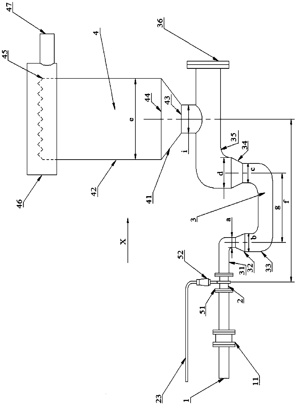
[0049] figure 1 The structure of the secondary coagulation system for continuous sludge dewatering according to the present invention is shown in one embodiment.

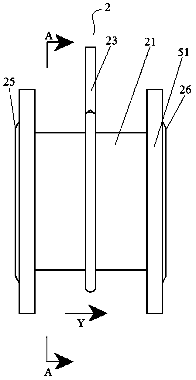
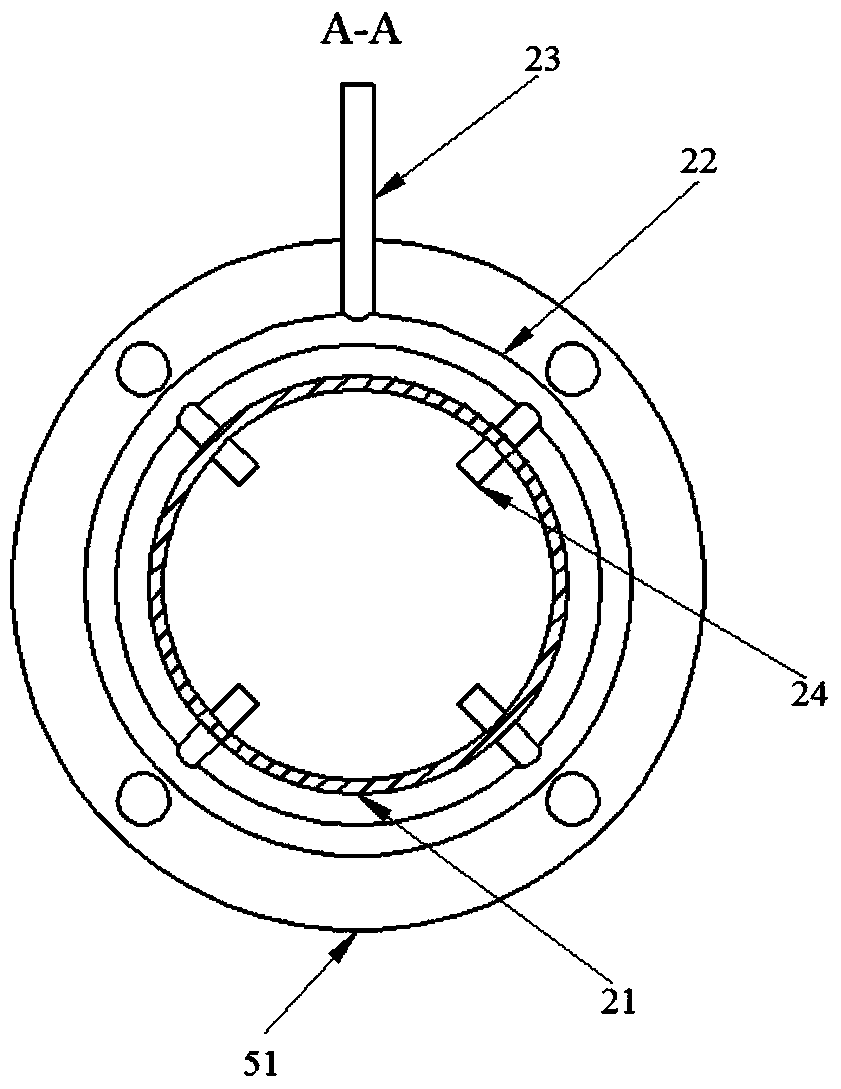
[0050] Such as figure 1 As shown, in the above embodiment, along the secondary coagulation system for continuous sludge dehydration, the liquid inlet pipe 1, the drug doser 2, the mixing pipe 3 and the coagulation cylinder 4 are sequentially included, wherein the mixing pipe 3 is It includes in turn: an inlet elbow 31 , an inlet reducing joint 32 , a U-shaped pipe 33 , an outlet reducing joint 34 and an outlet elbow 35 . To this end, ...


PUM


Abstract

The invention discloses a medicine feeder for continuous sludge dehydration. The medicine feeder comprises a pipe body, an outer ring pipe, a medicine feeding pipe and a plurality of branch pipes, wherein the two ends of the pipe body in the axial direction are provided with a liquid inlet and liquid outlet respectively; the outer ring pipe is arranged on the periphery of the pipe body; one end of the medicine feeding pipe extends out of the outer ring pipe, and the other end of the medicine feeding pipe is communicated with an internal space of the outer ring pipe. The branch pipes are arranged between the outer ring pipe and the pipe body and distributed in the circumference direction of the outer ring pipe, one end of each branch pipe is communicated with the internal space of the outer ring pipe, and the other end of the branch pipe is communicated with the inside of the pipe body. The invention further discloses a secondary coagulation system for continuous sludge dehydration. The secondary coagulation system comprises a liquid inlet pipe, the medicine feeder, a mixing pipe and a coagulation barrel which are sequentially connected in the flow direction of liquid. The coagulation barrel is provided with a clear liquid outlet. The medicine feeder enables a medicine to be quickly and evenly mixed with mixed liquid, so that the medicine and the mixed liquid react fully, and thus a flocculation effect in the mixing flocculation process is improved.

Description

technical field [0001] The invention relates to a material conveying device, in particular to a medicine conveying device. The invention also relates to a water treatment system, in particular to a waste water treatment system. Background technique [0002] The steel mill wastewater treatment station mainly treats industrial pollutants such as emulsion, concentrated alkali, concentrated tin liquid and acidic wastewater. The sludge generated during the wastewater treatment process enters the sludge suspension tank, is aerated and mixed to form a suspended solid liquid, and then a flocculant is added to cause a coagulation reaction, and then enters the sludge dewatering equipment for mud-water separation. Coagulation reaction is a very critical link in wastewater treatment, and its effect will directly affect the dehydration efficiency of dehydration equipment. [0003] In the coagulation process of wastewater treatment, since the suspended matter belongs to solid-liquid two...

Claims


Application Information

Patent Timeline
Patent Type & Authority Patents(China)
IPC IPC(8): C02F11/147
Inventor 李宏顾冠斌施曙涛
Owner BAOSHAN IRON & STEEL CO LTD
Why Eureka
Try Eureka