Installation method for fiber grating drill hole stress meter in deep coal seam

A technology of borehole stress gauge and installation method, which is used in earth-moving drilling, wellbore/well components, sealing/packaging, etc. Accurate and reliable results, simple equipment and tooling, elimination of pressure relief effects

Active Publication Date: 2017-01-04
BANDWEAVER TECH CO LTD
View PDF8 Cites 2 Cited by
  • Summary
  • Abstract
  • Description
  • Claims
  • Application Information

AI Technical Summary

Problems solved by technology

Among them, the in-line installation method is to drill a hole at the position to be measured in the coal seam, and then insert the strain gauge directly into the coal seam. Although this method is simple, the size of the borehole stress gauge itself is smaller than the borehole diameter. As a result, there is a gap between it and the surrounding coal seam, and it cannot be tightly attached to the coal seam. When the stress change is transmitted to the monitoring point, the actual stress is unloaded by the structural deformation of the borehole itself, and the stress measured by the borehole stress gauge is always smaller than the actual stress. Stress, even the measured value is 0, and the unloaded stress is related to the structure of the borehole and the nearby geological structure, so it cannot be quantitatively calculated, so the algorithm cannot be used to compensate for this stress, resulting in the measurement results of the borehole stress gauge Always too small, leading to delays in early warning, and even unforeseen casualties
[0004] The oil bag installation method is to wrap the sensor in the oil bag, insert the sensor into the borehole, and make the oil bag expand by adding oil to the oil bag to realize the close contact between the hole and the sensor, so as to make up for the difference between the borehole stress gauge and the sensor. gaps between coal seams, but this method has problems such as oil leakage and long-term maintenance
[0005] The grouting installation method is to inject cement and other fluid substances into the borehole through the grouting machine after the sensor is installed in the borehole. Since the depth of the borehole is about 10 meters, there is residual air at the bottom of the borehole after the grouting , due to the pressure of the air in the borehole, the shotcrete fluid cannot enter the bottom of the borehole, and the shotcrete fluid cannot completely cover the sensor, or even only cover the tail end of the sensor, which cannot fully ensure the close contact between the sensor and the coal seam. In actual use Little improvement in measurement compared to in-line
In addition, due to the grouting installation method, after the grouting fluid solidifies, the signal transmission cable, power cable, or transmission optical fiber of the sensor is completely wrapped, so that when cracks develop in the coal seam near the drilling hole, the signal transmission cable, power cable, or The transmission optical fiber is very easy to break and cannot be repaired after breaking

Method used


Image

  • Installation method for fiber grating drill hole stress meter in deep coal seam

Examples


Embodiment 1

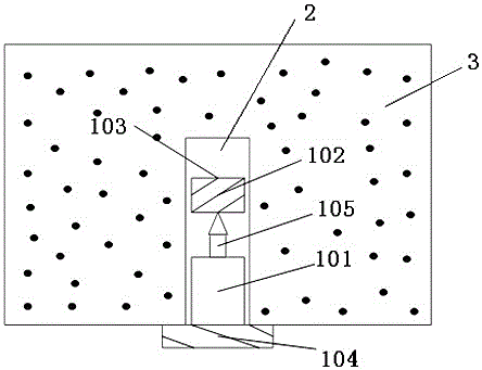
[0031] figure 1 It is a schematic structural diagram of Embodiment 1 of the present invention. As shown in the figure, the installation method of the drilling stress gauge of the present invention includes a drilling stress gauge 101 , glue 102 , glue stick 103 , flexible baffle 104 and nails 105 . The glue 102 is placed in the glue stick 103 , the flexible baffle 104 is installed at the tail of the drilling stress gauge 101 , and the nail 105 is installed at the front end of the drilling stress gauge 101 . Wherein, the glue stick structure is a thin film, and its influence on the stress induction of the optical fiber grating can be neglected. The glue is formed by mixing resin and catalyst at a volume ratio of 1:1. The glue can quickly penetrate into the fine cracks of coal and rock mass, and its hardness after solidification is similar to that of the coal seam structure. The size of the flexible baffle is larger than the diameter of the borehole.

[0032] The glue stick fi...

Embodiment 2

[0034]A thin blade (or other sharp device) is first inserted into the bottom of the drilled hole, with the drilled strain gauge in the glue stick containing the glue, which is fed into the drilled hole with the installation tool, when it reaches the drilled hole At the bottom, due to the existence of the blade, the glue stick will be cut and the glue will flow out. When the glue solidifies, the tight combination of the drilling stress gauge and the coal seam can be realized, and the continuity of the stress transmission of the coal seam can be realized.

Embodiment 3

[0036] First insert the borehole stress gauge into the bottom of the borehole, and then use a booster filled with glue to push the glue into the borehole. Make sure that the glue in the booster is enough to fill the gap between the borehole stress gauge and the surrounding coal seam Otherwise, air may enter when the glue is pushed in for the second time. After the glue is pushed in, the booster should be withdrawn in time. After the glue is solidified, the continuity of the stress transmission of the coal seam can also be achieved, making the measurement results true and accurate. precise.


PUM


Abstract

The invention relates to an installation method for a fiber grating drill hole stress meter in a deep coal seam. The installation method comprises the steps that the drill hole stress meter and glue are put into a drill hole of the deep coal seam; the void space between the drill hole stress meter and the drill hole is filled with the glue; the glue is solidified, and the drill hole stress meter and the coal seam form a stress whole; and the drill hole stress meter truly measures the disturbance of stress from the outside of the coal seam. According to the installation method for the fiber grating drill hole stress meter in the deep coal seam, the hardness of the solidified glue is similar to that of the coal seam structure, thus, the drill hole stress meter and the coal seam which are connected with the glue can be closely attached to each other, the coal seam stress transfer continuity is ensured, the measurement structure is more real and accurate, and the installation method can be used in various application occasions where close contact between measuring sensors and measuring holes needs to be achieved.

Description

technical field [0001] The invention relates to optical fiber sensing technology, in particular to an installation method of a borehole stress gauge used for real-time monitoring of coal and rock stress. Background technique [0002] my country is the world's largest coal-producing country. With the completion of shallow coal seam mining, my country's coal mining has gradually entered the field of deep mining. After the mining depth exceeds 600 meters, due to the gravity of the stratum, the high stress concentration areas of roadways and working faces are becoming more and more serious. The more the coal-rock dynamic disasters become more frequent. Because coal-rock dynamic disaster is a phenomenon with dynamic effects and disaster consequences that occurs in a short period of time under high external stress, its gestation, formation and occurrence are always closely related to coal-rock mass stress and energy accumulation and release. Therefore, mastering the stress-strain ...

Claims


Application Information

Patent Timeline
Patent Type & Authority Applications(China)
IPC IPC(8): E21B23/01E21B33/13
CPCE21B23/01E21B33/13
Inventor 张焰辉黄煜李飞庆方立新张静赵浩
Owner BANDWEAVER TECH CO LTD
Why Eureka
Try Eureka