Illumination system

A lighting system and light source technology, applied in the field of lighting systems, can solve the problems of reducing the service life of the shutter 40 and the coupling group 50, the workload of replacing components in the system, and the large volume of the lighting system, so as to save microlens arrays, improve service life, Effect of improving coupling efficiency

Inactive Publication Date: 2017-01-04
SHANGHAI MICRO ELECTRONICS EQUIP (GRP) CO LTD
View PDF7 Cites 3 Cited by
  • Summary
  • Abstract
  • Description
  • Claims
  • Application Information

AI Technical Summary

Problems solved by technology

Since the filter 52 is placed in the coupling group 50, the thermal load of the shutter 40 and the coupling group 50 is relatively large, and the higher heat is easy to burn the shutter 40, and the film layer of the coupling group 50 lenses deteriorates, thereby reducing the shutter 40. and the service life of the coupling group 50, not only brings unnecessary workload to the system replacement components, but also increases additional costs; the coupling group 50 adopts the structure of four spherical optical lenses 51, although it can meet certain illumination requirements, but There is a low coupling efficiency. When using a traditional lighting system, taking the uniform field of view of 54mm×34mm and the input power of the light source as an example, the energy entering the quartz rod 70 is 77.76W, and the energy of the uniform field of view spot is 60.546W. Lighttools simulation analysis, the simulation results are as follows figure 2 As shown, the results are as follows: pupil uniformity ellfield=0.26%, Ellcheck=0.14%; the simulation results of field uniformity are as follows image 3 As shown, its uniformity is 0.92%. In addition, the traditional lighting system still has problems such as large volume, high cost, and complicated structure.

Method used


Image

  • Illumination system
  • Illumination system
  • Illumination system

Examples


Embodiment 1

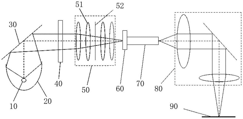
[0037] A lighting system provided by the invention, such as Figure 4 As shown, the light source 110, the filter 120, the shutter 130, the coupling group 140, the quartz rod 150, the relay group 160 and the mask surface 170 are sequentially included along the propagation direction of the light beam. In this embodiment, the light source 110 is a mercury lamp Light source 111, described mercury lamp light source 111 provides the energy source of required NA (numerical aperture) for illumination system; Also comprises ellipsoid reflective bowl 112 and cold light mirror 113 between described mercury lamp light source 111 and described filter plate 120 , the mercury lamp light source 111 is located at a focal point of the ellipsoidal reflective bowl 112, and the function of the ellipsoidal reflective bowl 112 is to gather light emitted from one focal point to another focal point; the mercury lamp light source 111 The emitted light beam is reflected by the ellipsoidal reflecting bow...

Embodiment 2

[0049] Compared with Example 1, also with Figure 4 For example, the difference of this embodiment is: when the NA of the coupling group 140 on the mask surface 170 is 0.1, please refer to Figure 10 , the radius of curvature R1=500mm of the first optical surface 143; the radius of curvature R2=-30.499mm of the second optical surface 144, the conic coefficient K=-1.211 of the second optical surface 144, the effective focal length f=64.218, and the central thickness d =45mm, outer diameter D=90mm; the aspheric lens is made of fused silica (F-SILICA), wherein the refractive index Nd=1.4585, Abbe number νd=67.79.

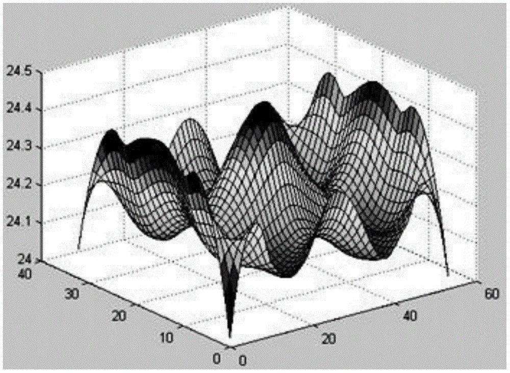
[0050] In this embodiment, the quartz rod 150 has a square structure, the end surface size is 17.2mm×17.2mm, the length is 400mm, the uniform field of view is 45mm×45mm, the input power of the light source 110 is 100W, and the energy entering the quartz rod 150 is 92.582W , the energy received on the mask surface 170 is 92.503W; the energy of uniform field of view spo...

Embodiment 3

[0053] Compared with Embodiments 1 and 2, the difference of this embodiment is that: the light source 210 is an LED light source. Please focus on reference Figure 11 , the light beam emitted by the LED light source 210 is filtered by the filter 220, and then incident on the coupling group 240 through the shutter 230, and the light beam coupled by the aspheric lens in the coupling group 240 passes through the quartz rod 250 for more than The light is incident to the relay group 260 after being homogenized after the second reflection, and is imaged on the mask surface 270 after being enlarged by the relay group 260 .

[0054] The lighting system provided by this embodiment also has the advantages of high coupling efficiency, small size, low cost, and prolongs the service life of the shutter 230 and the coupling group 240 .

[0055] In summary, an illumination system provided by the present invention sequentially includes a light source, a filter, a shutter, a coupling group, a...


PUM

PropertyMeasurementUnit
wavelengthaaaaaaaaaa
thicknessaaaaaaaaaa
thicknessaaaaaaaaaa

Abstract

The invention relates to an illumination system, which sequentially comprises a light source, a filter, a shutter, a coupling group, a quartz rod, a relay group and a mask surface along the propagation direction of a light beam, wherein the coupling group adopts an aspheric lens, the filter, the aspheric lens, the quartz rod and the relay group are positioned on the same optical axis, the light beam emitted from the light source is subjected to filtering through the filter, and then is incident on the aspheric lens through the shutter, the light beam coupled through the aspheric lens is subjected to light balancing through the quartz rod and then is incident on the relay group, and the obtained light beam is amplified by the relay group and then is imaged on the mask surface. According to the present invention, the aspheric lens is used as the coupling group, such that the number of the coupling group lenses is reduced, the transmittance of the system is increased, the spherical aberration of the coupling system is reduced, and the coupling efficiency of the system is improved; and the filter is placed between the light source and the shutter, such that the temperatures of the shutter and the coupling group are substantially reduced, and the service lives of the shutter and coupling group are prolonged.

Description

technical field [0001] The invention relates to the field of photolithography equipment, in particular to an illumination system. Background technique [0002] Most of the existing semiconductor manufacturing adopts photolithography technology, which is used to print characteristic patterns on the surface of the substrate. The frequently used substrates are semiconductor wafers or glass substrates coated with light-sensitive media on the surface. During the lithography process, the wafer is placed on the wafer stage, and the characteristic pattern is projected onto the wafer surface through the exposure device in the lithography equipment. During this process, the illumination of the silicon wafer surface is an important parameter of the lithography machine, and its size will be It affects the exposure time of the photoresist, which in turn affects the productivity of the photolithography machine. At present, improving the illumination of the lighting system is an urgent pr...

Claims


Application Information

Patent Timeline
Patent Type & Authority Applications(China)
IPC IPC(8): G03F7/20
Inventor 刘柱景磊
Owner SHANGHAI MICRO ELECTRONICS EQUIP (GRP) CO LTD
Why Eureka
Try Eureka