MWT solar cell module

A technology of solar cells and solar energy, applied in the field of solar cells, can solve problems such as optical loss, achieve the effects of increasing fill factor, reducing power consumption, and increasing light-receiving area

Inactive Publication Date: 2017-01-04
JA SOLAR TECH YANGZHOU
View PDF6 Cites 14 Cited by
  • Summary
  • Abstract
  • Description
  • Claims
  • Application Information

AI Technical Summary

Problems solved by technology

The front of the battery is the light-receiving surface, and the coverage of the main grid lines and thin grid lines of the metal electrodes on the front will inevitably cause a part of the incident sunlight to be reflected by the metal electrodes, resulting in a part of optical loss

Method used


Image

  • MWT solar cell module
  • MWT solar cell module
  • MWT solar cell module

Examples


Embodiment 1

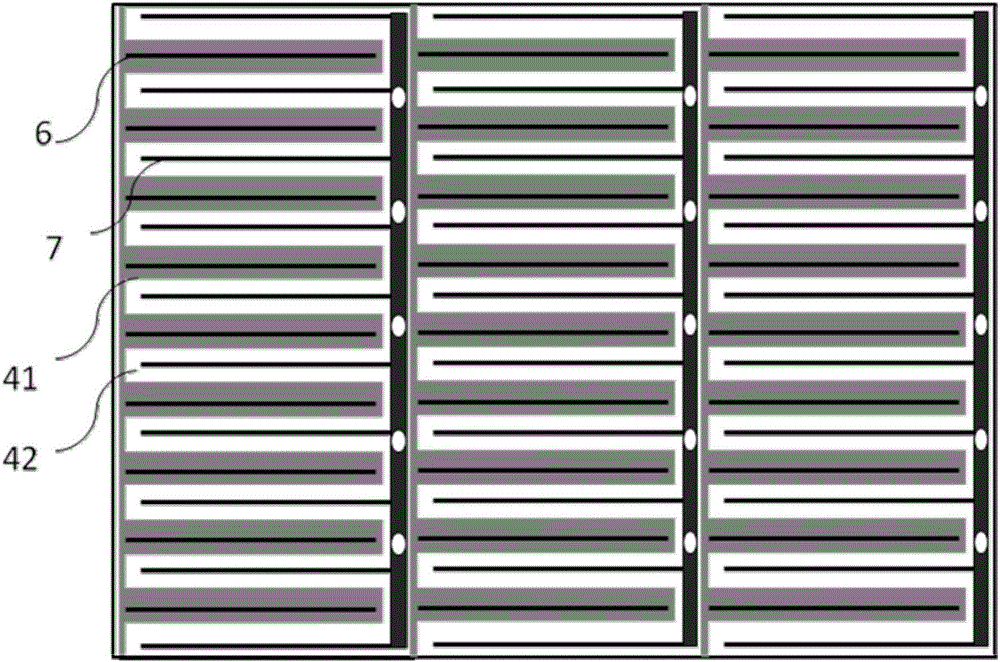
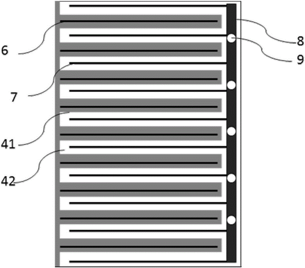
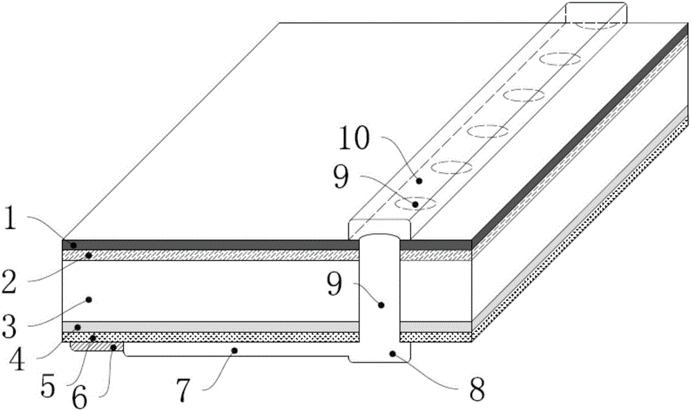
[0027] Such as Figure 1-5 As shown, the MWT solar cell assembly provided in this embodiment includes a plurality of MWT small solar cells connected in series, and the MWT solar small cells are cut from MWT solar cells, and the MWT solar small cells include n-type silicon substrate 3. The back side of the n-type silicon substrate is provided with n+ doped regions 41 and p+ doped regions 42 parallel to each other and alternately arranged, and a passivation layer 5 is provided on the n+ doped regions 41 and p+ doped regions 42 (ie, the back side passivation film), the passivation layer 5 is provided with a positive electrode fine grid 7 and a negative electrode fine grid 6, the positive electrode fine grid 7 is located on the passivation layer 5 corresponding to the p+ doped region 41 and is doped with p+ The region 41 is in contact, the negative electrode fine grid 6 is located on the passivation layer 5 corresponding to the n+ doped region 41 and is in contact with the n+ dope...

Embodiment 2

[0059] The difference from Example 1 is that the doped region of the MWT solar cell module is slightly changed, and the positions of the p+ doped region and the n+ doped region are exchanged. Similarly, the positions of the positive electrode fine grid and the negative electrode fine grid are also interchanged, while the busbar position remains the same.


PUM


Abstract

The invention discloses an MWT solar cell module in which only one electrode of each MWT solar cell is provided with a back main gate for being connected with a corresponding fine gate line. The back main gate guides current to front main gate of the corresponding MWT solar cell by virtue of a plurality of small holes passing through the corresponding MWT solar cell from top and bottom. The other electrode of each MWT solar cell has a fine gate and no main grid. The MWT solar cell module of the invention does not have any gate line on the front side to shield the light, and there is no gap between the MWT solar cells so that the efficiency of the module is improved. Since a plurality of cells are divided, the current of each cell strings is reduced so as to decrease the impact of thin gate line resistance loss, thereby reducing the consumption of silver paste and increasing the fill factors the cells and the MWT solar cell module.

Description

technical field [0001] The invention belongs to the field of solar cells, and in particular relates to a MWT solar cell component. Background technique [0002] A solar cell is a semiconductor device that converts light energy into electrical energy. Lower production costs and higher energy conversion efficiency have always been the goals pursued by the solar cell industry. For conventional solar cells at present, the negative electrode contact electrode and the positive electrode contact electrode are respectively located on the front and back sides of the battery sheet. The front of the battery is the light-receiving surface, and the coverage of the front metal electrode main grid lines and thin grid lines will inevitably cause a part of the incident sunlight to be reflected by the metal electrodes, resulting in a part of optical loss. The coverage area of ​​the front metal electrode of an ordinary crystalline silicon solar cell is about 7%, and reducing the front coverag...

Claims


Application Information

Patent Timeline
Patent Type & Authority Applications(China)
IPC IPC(8): H01L31/0224H01L31/068H01L31/05
CPCH01L31/02245H01L31/0516H01L31/0682Y02E10/547
Inventor 蒋秀林徐礼刘强薛文娟单伟
Owner JA SOLAR TECH YANGZHOU
Why Eureka
Try Eureka