Dual-rotor permanent-magnet DC servo speed measurement machine unit

A DC servo and permanent magnet technology, applied in the direction of magnetic circuit shape/style/structure, electromechanical devices, electric components, etc., can solve the problems of linearity error of output characteristics of tachogenerator, high manufacturing cost of the unit, low-speed failure, etc., to achieve The effect of stable operation, compact structure and small linear error

Active Publication Date: 2017-01-04
JIAXING UNIV
View PDF6 Cites 1 Cited by
  • Summary
  • Abstract
  • Description
  • Claims
  • Application Information

AI Technical Summary

Problems solved by technology

[0003] At present, DC servo tachometer units are often used. The manufacturing process is generally that the servo motor and the tachometer share the same shaft, but the stator and rotor windings (or the cup body of the cup-shaped rotor) are of two-stage structure. Therefore, the overall shape of the tachometer unit Most of them are slender and large in size, and the manufacturing cost of the unit is also high
In addition, for the DC servo tachometer unit, the tachometer generator used is a DC tachometer generator, and its armature circuit includes brushes and commutator segments, which will generate corresponding contact resistance, resulting in linearity errors and low speed in the output characteristics of the tachometer generator. failure zone

Method used


Image

  • Dual-rotor permanent-magnet DC servo speed measurement machine unit
  • Dual-rotor permanent-magnet DC servo speed measurement machine unit
  • Dual-rotor permanent-magnet DC servo speed measurement machine unit

Examples


Embodiment Construction

[0027] The implementation of a double-armature permanent magnet DC servo speed measuring unit of the present invention will be further described below in conjunction with the accompanying drawings.

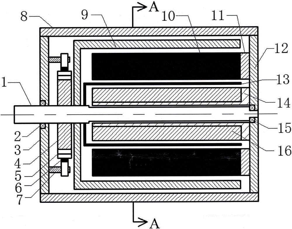
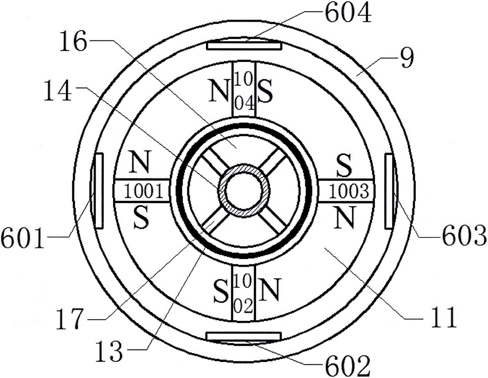
[0028] like figure 1 , figure 2 As shown, a dual-rotor permanent magnet DC servo tachometer unit includes a rotating shaft 1, a front end cover bearing 2, a front end cover 3, an insulating sleeve 4, a commutator 5, a brush 6, a brush bracket 7, and a casing 8 , slotless rotor 9, permanent magnetic steel 10, outer stator core 11, rear end cover 12, cup rotor 13, copper sleeve 14, rear end cover bearing 15, inner stator core 16 and Hall element 17;

[0029] The rotating shaft 1 passes through the front end cover bearing 2, the insulating sleeve 4, the slotless rotor 9, the cup rotor 13, the central hole of the copper sleeve 14 and the rear end cover bearing 15 in sequence, and passes through the front end cover 3 and the rear end cover 12 respectively. fixed with the casing 8; ...


PUM


Abstract

A dual-rotor permanent-magnet DC servo speed measurement machine unit comprises a rotation shaft, an electric brush, a support, a commutator, an insulation sleeve, a slotless rotor, an external stator core, permanent-magnet magnetic steel, a cup-shaped rotor, an internal stator core, a Hall component, a copper sleeve, an enclosure, a front end cover, a rear end cover and bearings, wherein the rotation shaft sequentially passes through the front end cover bearing, the insulation sleeve, the slotless rotor, the cup-shaped rotor, a copper sleeve central hole and the rear end cover bearing and are fixed with the enclosure respectively by the front end cover and the rear end cover, a winding of the slotless rotor is connected with the electric brush by the commutator, the commutator is fixed on the rotation shaft by the insulation sleeve, the Hall component is fixed in the internal stator core, the permanent-magnet steel is fixed in the external stator core, and a cup body of the cup-shaped rotor is arranged in a gap between the internal stator core and the external stator core. In the dual-rotor permanent-magnet DC servo speed measurement machine unit disclosed by the invention, an electric motor and a speed measurement device share the same magnetic field and the rotation shaft, the dual-rotor permanent-magnet DC servo speed measurement machine unit is compact in structure, small in size and stable in running, moreover, a signal of the speed measurement device is output in a brushless manner, the linear error is low, and no low-speed failure region is generated.

Description

technical field [0001] The invention relates to a DC servo speed measuring unit, more specifically to a double-rotor permanent magnet DC servo speed measuring unit. Background technique [0002] The servo motor, also known as the executive motor, is used as an actuator in the automatic control system to convert the input voltage signal into the angular displacement or angular velocity output of the rotating shaft. Servo motors can be divided into DC servo motors and AC servo motors according to the nature of the power supply. Among them, the instantaneous rotational angular velocity information is an important parameter of the servo motor. Through the measurement of the rotational angular velocity, the monitoring of the operating state of the servo motor can be realized, and the servo motor can be controlled according to the production requirements. [0003] At present, DC servo tachometer units are often used. The manufacturing process is generally that the servo motor and...

Claims


Application Information

Patent Timeline
Patent Type & Authority Applications(China)
IPC IPC(8): H02K16/00H02K1/17H02K11/21
CPCH02K1/17H02K16/00
Inventor 赵浩冯浩刘青松王璇
Owner JIAXING UNIV
Why Eureka
Try Eureka