Ionic liquid nanolayer of laser printer rubber covered roller, rubber covered roller and preparation method thereof

A technology of laser printers and ionic liquids, applied in the fields of optics, electrical recording process equipment using charge graphics, and electrical recording technology, can solve the problem of high-quality draft printing and high-definition requirements, developing rollers and charging rollers Difficult to meet high electrical conductivity, rubber roller roughness, resilience and hardness effects, etc., to achieve high-quality print output, good electrical conductivity, and high mixing uniformity

Inactive Publication Date: 2017-01-18
SHENZHEN LEPUTAI TECH CO LTD
View PDF15 Cites 0 Cited by
  • Summary
  • Abstract
  • Description
  • Claims
  • Application Information

AI Technical Summary

Problems solved by technology

The conductive fillers added in the above-mentioned patents all have a limitation on the amount of addition. When the amount of addition is small, the coating has little effect on the overall appearance, color, and mechanical properties of the rubber roller, and there will be no precipitation, whitening, etc. on the surface of the rubber body. problems such as frost, but the high conductivity of the developing roller and charging roller is basically difficult to satisfy
When too much conductive filler is added to meet high conductivity, inorganic fillers such as carbon black, graphite, metal fiber, and metal powder are generally not only prone to sedimentation and poor uniformity and stability, but also have problems such as excessive addition of the rubber roller. degree, resilience and hardness have a great influence
However, when too much small molecule salt is added, problems such as precipitation on the surface of the main material and white frost will easily occur.
All of these have had a great impact on the high-quality printout and the overall performance of the device, making it difficult to meet the requirements for high-quality draft printing and high-definition

Method used


Image

  • Ionic liquid nanolayer of laser printer rubber covered roller, rubber covered roller and preparation method thereof
  • Ionic liquid nanolayer of laser printer rubber covered roller, rubber covered roller and preparation method thereof
  • Ionic liquid nanolayer of laser printer rubber covered roller, rubber covered roller and preparation method thereof

Examples


preparation example Construction

[0037] The present invention also provides a preparation method for the above-mentioned laser printer rubber roller, comprising the steps of:

[0038] S1 Clean the surface of the laser printer rubber roller with only rubber body (not sprayed with conductive paint) with a surfactant (such as detergent, etc.), and then rinse the surfactant with clean water until the surfactant is completely removed;

[0039] S2 Dry the rubber roller treated in step S1 with an air gun, then place the rubber roller in the plasma generator, first vacuum 0-30Pa, feed air, adjust the pressure to 10-50Pa, and turn on the plasma generator. Plasma generator, the rubber roller is subjected to plasma treatment, the treatment power is 50-300W and the treatment time is 30s-200s;

[0040] S3 Place the rubber roller on a dipping machine with a rotating speed of 50rpm-1000rpm, immerse it in the small molecule ionic liquid or / and ionic liquid polymer, or the mixture of the above-mentioned liquid or the mixture ...

Embodiment 1

[0045] S1 Use a surfactant to clean the rubber roller that only has a rubber body (silicone rubber), and then rinse it with clean water until the surfactant is completely removed;

[0046] S2 Dry the rubber roller with an air gun. The plasma machine is first evacuated to 25Pa, and air is introduced to adjust the pressure to 50Pa. Then, the rubber roller is placed in the plasma machine for plasma treatment. The treatment time is 120s and the treatment power is 90W;

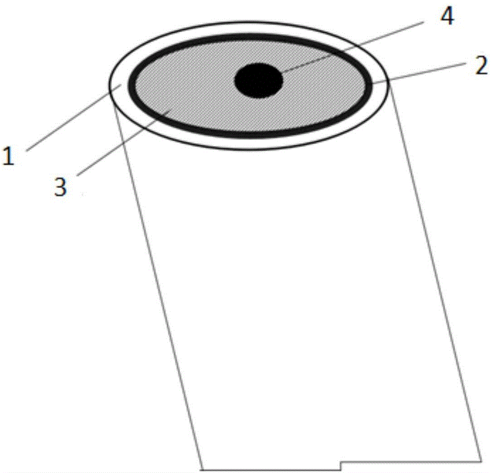
[0047] S3 fixes the silicone rubber cot after the last step on the dipping machine, and the ionic liquid polymer is (n=7) 20 parts, dilute with 10 parts of ethanol solvent, immerse the rubber roller in the ionic liquid polymer after dilution, dip coater is adjusted to rotating speed 100rpm, time 3s, at this moment ionic polymer nano-layer thickness is about 20nm, after standing for 20min, place it in a warm drying oven at 100°C and dry for 60min;

[0048] In S4, the outer periphery of the rubber roller after dryi...

Embodiment 2

[0050] S1 Use a surfactant to clean the rubber roller with only rubber body (synthetic rubber), then rinse with water until the surfactant is completely removed;

[0051] S2 Dry the rubber roller with an air gun. The plasma machine is first evacuated to 20Pa, and air is introduced to adjust the pressure to 40Pa. Then, the rubber roller is placed in the plasma machine for plasma treatment. The treatment time is 200s and the treatment power is 70W;

[0052] S3 Fix the synthetic rubber roller treated in the previous step on the dipping machine, and use ionic liquid A total of 30 parts (the ratio of the two is 5:3), the rubber roller is immersed in the diluted ionic liquid, the dipping machine is adjusted to a rotating speed of 200rpm, and the time is 15s. At this time, the thickness of the ionic liquid nano layer is about 15nm. Dry in a warm drying oven at a temperature of 80°C for 60 minutes;

[0053] S4 After the drying in the previous step, the outer circumference of the rub...


PUM


Abstract

The invention provides an ionic liquid nanolayer of a laser printer rubber covered roller. The ionic liquid nanolayer contains a micromolecular ionic liquid or ionic liquid polymer or the mixture of the liquid or/and the polymer and dispersion liquid. The laser printer rubber covered roller comprise a rubber covered roller rubber body and an outer-layer coating, wherein the ionic liquid nanolayer is arranged between the rubber covered roller rubber body and the outer-layer coating and is 0.1-200 nm in thickness. A preparation method of the laser printer rubber covered roller comprises the steps that the rubber covered roller provided with a rubber layer is cleaned in a standardized mode; then the rubber covered roller is blow-dried for plasma treatment; then the rubber covered roller is put on a dip-coating machine and is dipped with ionic liquid to form the nanolayer, the periphery of the rubber covered roller is dried and is sprayed with a conductive coating. The ionic liquid nanolayer can form a double electrode layer structure between conductive rubber and the conductive coating, the conductive performance of the laser printer rubber covered roller is further improved, the conductive performance of the laser printer rubber covered roller can be stabilized, a system is stable and homogeneous, and accordingly high-quality printed rough sketch output is provided.

Description

technical field [0001] The invention belongs to the technical field of laser imaging, and in particular relates to an ionic liquid nano-layer for a rubber roller of a laser printer, a rubber roller with the ionic liquid nano-layer and a preparation method for the rubber roller. Background technique [0002] The core imaging device of a laser printer is the toner cartridge, and the developing roller and the charging roller are one of the important components. When the developing roller is working, it mainly absorbs the toner through the charge on the surface of the rubber roller. After the printing data is converted and processed, it is converted into a corresponding laser signal. The charging roller is used to charge the toner cartridge, and then refracted to the OPC surface through the prism to complete the process. Subsequent printouts work. Therefore, complete and high-quality drawing output has strict requirements on the stable and high conductivity of the charging roll...

Claims


Application Information

Patent Timeline
Patent Type & Authority Applications(China)
IPC IPC(8): G03G15/02G03G15/10
CPCG03G15/0233G03G15/10
Inventor 徐秀茹孟鸿袁星羊辉
Owner SHENZHEN LEPUTAI TECH CO LTD
Why Eureka
Try Eureka