Thermal power plant desulfurization wastewater electrodialysis reconcentrator

A technology of desulfurization wastewater and electrodialysis, which is applied in water/sewage treatment, heating water/sewage treatment, oxidized water/sewage treatment, etc. It can solve the problems of long process flow, low recovery rate control of the system, and high treatment cost. Achieve the effects of reducing investment and operating costs, reducing the chance of fouling, and high concentration multiples

Inactive Publication Date: 2017-01-25
刘永锋
View PDF3 Cites 5 Cited by
  • Summary
  • Abstract
  • Description
  • Claims
  • Application Information

AI Technical Summary

Problems solved by technology

The disadvantages of using evaporation and crystallization to treat desulfurization wastewater are: high investment, because all desulfurization wastewater is evaporated, and the operating cost is very high
Due to the high salt content of desulfurization wastewater and rich in organic matter and scaling substances, reverse osmosis is used to concentrate and reduce the amount, the pretreatment process requires strict requirements, and the recovery rate of the system is controlled at a low level, generally around 50%. The salinity of the brine increases to about 70000ppm, disposing of such brine will be a huge cost and challenge for the desalination industry, resulting in longer start-up preparation time and higher water cost
Nanofiltration is used to reduce the amount of desulfurization wastewater. The removal rate of nanofiltration for monovalent ions is too high, and the produced water cannot be directly reused. Further desalination of nanofiltration produced water is required to meet the reuse requirements. The process is relatively long and the treatment cost higher

Method used


Image

  • Thermal power plant desulfurization wastewater electrodialysis reconcentrator

Examples


Embodiment Construction

[0014] The present invention will be further described in conjunction with the accompanying drawings and specific embodiments.

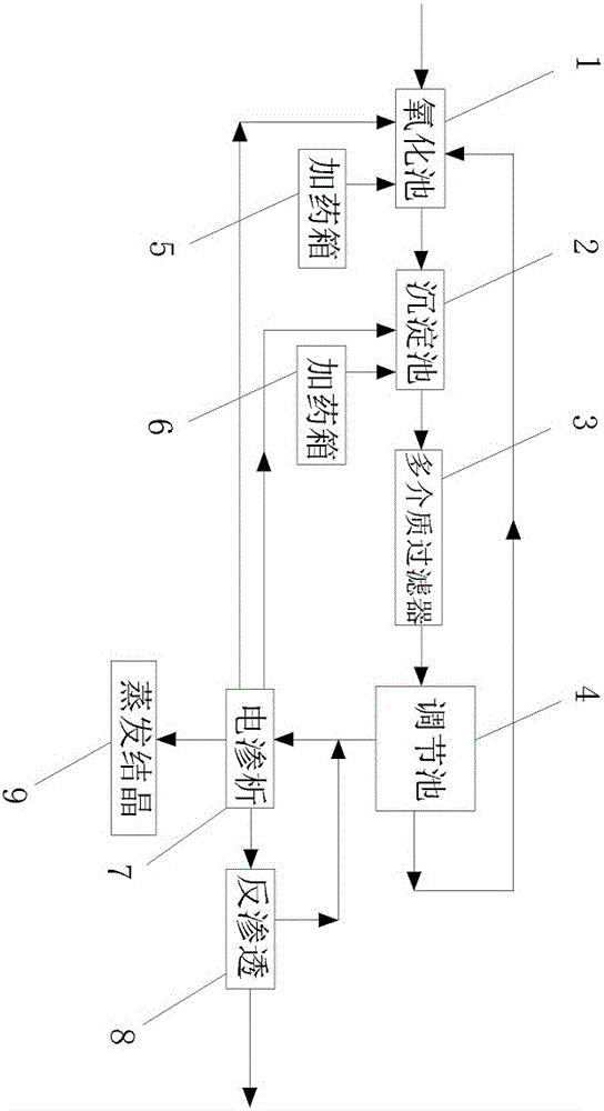
[0015] As a specific example, such as figure 1 shown, see figure 1 , an electrodialysis reconcentration device for desulfurization wastewater in a thermal power plant, comprising an oxidation tank 1, a sedimentation tank 2, a multimedia filter 3, a regulating tank 4, an electrodialysis device 7, a reverse osmosis device 8, an evaporation crystallization device 9, a first adding Medicine box 5 and second medicine box 6;

[0016] The inlet of the sedimentation tank 2 communicates with the outlet of the oxidation tank 1 and the inlet of the multimedia filter 3, the outlet of the multimedia filter 3 communicates with the inlet of the regulating pond 4, and the first of the regulating pond 4 The outlet is connected with the inlet of the oxidation tank 1, the second outlet of the regulating tank 4 is connected with the inlet of the electrodialysis device...


PUM


Abstract

The invention relates to an industrial wastewater treatment technique and device, particularly a thermal power plant desulfurization wastewater electrodialysis reconcentrator. An inlet of a precipitation tank communicates with an outlet of an oxidation tank and an inlet of a multimedia filter; an outlet of the multimedia filter communicates with an inlet of a regulating tank; a first outlet of the regulating tank communicates with an inlet of the oxidation tank; a second outlet of the regulating tank communicates with an inlet of an electrodialysis plant; a cathode water outlet of the electrodialysis plant communicates with the inlet of the precipitation tank; an anode water outlet of the electrodialysis plant communicates with the inlet of the oxidation tank; an electrodialysis concentrated water outlet of the electrodialysis plant communicates with an inlet of an evaporative crystallizer; an electrodialysis fresh water outlet of the electrodialysis plant communicates with an inlet of an reverse osmosis unit; an outlet of a first dosing tank communicates with the inlet of the oxidation tank; and an outlet of a second dosing tank communicates with the inlet of the precipitation tank. The thermal power plant desulfurization wastewater electrodialysis reconcentrator has high electrodialysis weight concentration, reduces the subsequent evaporative crystallization load, and lowers the investment and operating cost.

Description

technical field [0001] The invention relates to an industrial wastewater treatment process and device, in particular to an electrodialysis reconcentration device for desulfurization wastewater in a thermal power plant. Background technique [0002] At present, the common desulfurization wastewater treatment processes in thermal power plants at home and abroad are mainly: hydraulic ash removal, separate chemical treatment systems (mainly triple box treatment), evaporation and other methods. Among them, the evaporation treatment is to separate the desulfurization wastewater into high-quality water vapor and solid waste through evaporation and crystallization devices, so as to realize zero discharge of wastewater in the whole plant. The disadvantages of using the evaporation and crystallization method to treat desulfurization wastewater are: the investment is high, and the operation cost is high because all the desulfurization wastewater is evaporated. Therefore, it is necessa...

Claims


Application Information

Patent Timeline
Patent Type & Authority Applications(China)
IPC IPC(8): C02F9/10
CPCC02F9/00C02F1/001C02F1/04C02F1/441C02F1/4693C02F1/52C02F1/76
Inventor 刘永锋巫立斌
Owner 刘永锋
Why Eureka
Try Eureka