Method and device for detecting flight time performance of positron emission tomography system

A technology of positron emission and time-of-flight, which is applied in measuring devices, radiation measurement, X/γ/cosmic radiation measurement, etc., can solve the problems of high cost and complex implementation process of time-of-flight performance detection, and achieve high reliability Effect

Active Publication Date: 2017-01-25
SHANGHAI UNITED IMAGING HEALTHCARE
View PDF5 Cites 9 Cited by
  • Summary
  • Abstract
  • Description
  • Claims
  • Application Information

AI Technical Summary

Problems solved by technology

[0006] The present invention solves the problems of complex implementation process and high cost of the time-of-flight performance detection of the existing positron emission tomography imaging system

Method used


Image

  • Method and device for detecting flight time performance of positron emission tomography system
  • Method and device for detecting flight time performance of positron emission tomography system
  • Method and device for detecting flight time performance of positron emission tomography system

Examples


Embodiment Construction

[0026] In order to make the above objects, features and advantages of the present invention more clearly understood, the specific embodiments of the present invention will be described in detail below with reference to the accompanying drawings.

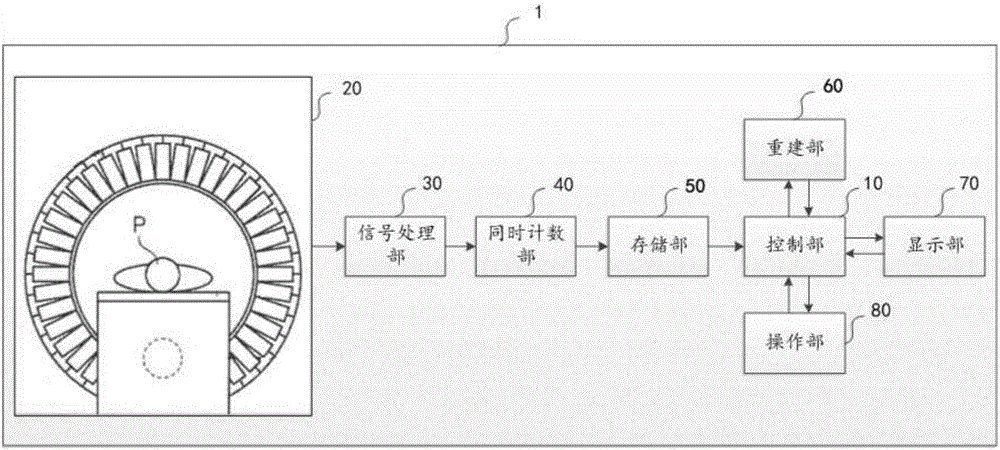
[0027] In one embodiment of the present invention, as figure 1 As shown, the PET apparatus 1 has a control unit 10 as a center, and includes a rack 20 , a signal processing unit 30 , a coincidence unit 40 , a storage unit 50 , a reconstruction unit 60 , a display unit 70 , and an operation unit 80 .

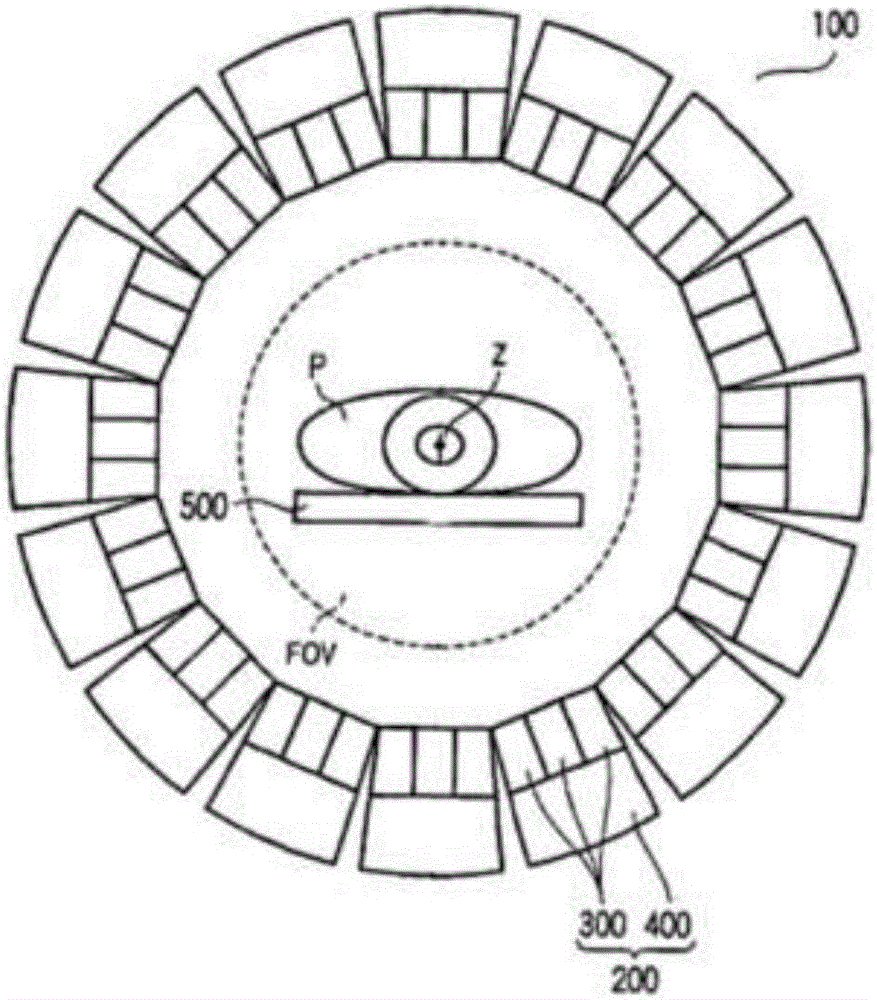
[0028] figure 2 A schematic cross-sectional view of the detector ring 100 configured on the gantry 20. The gantry 20 has a detector array composed of a plurality of detector rings 100 arranged along the central axis Z of the circumference. The detector ring 100 has a plurality of detectors 200 arranged on a circumference around the central axis Z. A field of view (FOV) is formed on the opening of the detector ring 100 . The bed 500...


PUM


Abstract

The invention provides a method and a device for detecting the flight time performance of a positron emission tomography system. The method comprises the following steps: performing data acquisition on detected objects distributed according to an activity rule by using a system; performing a back projection operation with flight time information on acquired data to obtain first back projection data; performing a back projection operation without the flight time information on the acquired data to obtain second back projection data; comparing the first back projection data with the second back projection data, and acquiring the flight time performance of the system according to comparison data. By adopting the method and the device, the flight time performance of the system can be detected conveniently and efficiently.

Description

technical field [0001] The invention relates to a positron emission tomography imaging system, in particular to the technical field of performance detection of a positron emission tomography imaging system. Background technique [0002] Positron Emission Tomography (PET) has become an important molecular imaging tool for pre-clinical research and clinical diagnosis. Electron annihilation emits two photon pairs with opposite directions and equal energy. Each photon travels at the speed of light. After the PET detector detects the photon pair, a series of signal processing is performed to reconstruct an image with clinical diagnostic significance. [0003] With the development of photomultiplier tubes, crystals, circuits and computer technology, it has become feasible to calculate the precise location of the photon occurrence (i.e. the emission location of the positron, that is, the location of the decay of the tracer) from the photon time-of-flight difference, the diameter of...

Claims


Application Information

Patent Timeline
Patent Type & Authority Applications(China)
IPC IPC(8): G01T1/29G01T7/00
CPCG01T1/2985G01T7/00A61B6/037G01T1/202
Inventor 邓子林
Owner SHANGHAI UNITED IMAGING HEALTHCARE
Why Eureka
Try Eureka