Power grid fault ultrasonic testing device and method

A detection device and a technology for power grid faults, which are applied to measuring devices, using sound waves/ultrasonic waves/infrasonic waves to analyze solids, and using sound waves/ultrasonic waves/infrasonic waves for material analysis, etc., can solve the problems of increasing labor intensity of staff, affecting power supply reliability, and faults Frequent and complex problems, to achieve the effect of friendly operation interface, light weight and wide application range

Pending Publication Date: 2017-02-01
HENAN HONGBO MEASUREMENT & CONTROL
View PDF9 Cites 5 Cited by
  • Summary
  • Abstract
  • Description
  • Claims
  • Application Information

AI Technical Summary

Problems solved by technology

[0002] China's distribution network has the characteristics of complex line structure, diverse environment, frequent and complex faults, and heavy maintenance workload. With the development of power systems, the improvement of voltage levels and automation, the insulation problems of power equipment have become more and more prominent. When a fault occurs in a certain section of the distribution line, it is necessary to check the location of the fault one by one. This not only requires a lot of work, but also delays the repair time and affects the reliability of power supply. This undoubtedly increases the labor intensity of the staff. For power companies, ensuring The safety, reliability, stability, and economic operation of equipment are the basis for its survival and development. Any defect or failure of equipment in the production system may affect safe production. At present, the industry needs a real-time monitoring of the power grid. Detection device to solve

Method used


Image

  • Power grid fault ultrasonic testing device and method
  • Power grid fault ultrasonic testing device and method
  • Power grid fault ultrasonic testing device and method

Examples


Embodiment 1

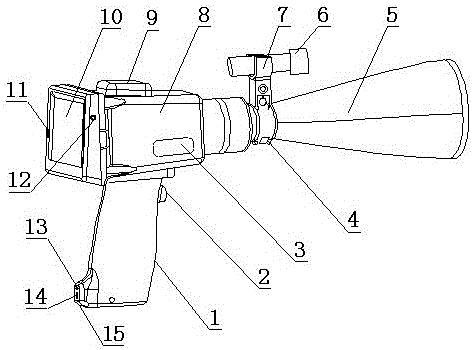
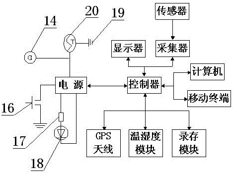
[0022] Such as figure 1 , figure 2 and image 3 As shown, a power grid fault ultrasonic detection device and detection method thereof, it includes a nacelle 8, the bottom of the nacelle 8 is connected with a handle 1, the front end of the handle 1 is provided with an intelligent switch 2, the handle 1 is provided with a charging hole 14 and a charging indicator light 13, the handle 1 is provided with an anti-drop device 15, and the front part of the cabin 8 is provided with a signal converter 4, and the signal converter 4 is connected to Round table receiver 5, the top of described round table receiver 5 is equipped with sight bracket 7, and described sight bracket 7 is equipped with laser sight 6, and the top of described nacelle 8 is equipped with GPS antenna 9, described The back of the cabin 8 is connected with a display 10, the cabin 8 is provided with a USB interface 11 and an earphone jack 12, the display 10 is connected with a controller, and the controller is conne...

Embodiment 2

[0030] Such as figure 1 , figure 2 and image 3As shown, a power grid fault ultrasonic detection device and detection method thereof, it includes a nacelle 8, the bottom of the nacelle 8 is connected with a handle 1, the front end of the handle 1 is provided with an intelligent switch 2, the handle 1 is provided with a charging hole 14 and a charging indicator light 13, the handle 1 is provided with an anti-drop device 15, and the front part of the cabin 8 is provided with a signal converter 4, and the signal converter 4 is connected to Round table receiver 5, the top of described round table receiver 5 is equipped with sight bracket 7, and described sight bracket 7 is equipped with laser sight 6, and the top of described nacelle 8 is equipped with GPS antenna 9, described The back of the cabin 8 is connected with a display 10, the cabin 8 is provided with a USB interface 11 and an earphone jack 12, the display 10 is connected with a controller, and the controller is connec...


PUM


Abstract

The invention relates to a power grid fault ultrasonic testing device and method. The device comprises an engine room. A handle is connected to the bottom of the engine room. An intelligent switch is arranged on the front end face of the handle. A charging hole and a charging indicator lamp are arranged on the lower portion of the handle. The handle is provided with an anti-falling device. The front portion of the engine room is provided with a signal converter. The signal converter is connected with a cone frustum receiver. A sighting device support is installed on the top of the cone frustum receiver. A laser sight is installed on the sighting device support. A GPS antenna is installed on the top of the engine room. A displayer is connected to the back of the engine room. The engine room is provided with a USB interface and an earphone jack. The displayer is connected with a controller. The controller is connected with a humidity and temperature module and a recording and storing module. The power grid fault ultrasonic testing device has the advantages of being reasonable in design, low in weight, convenient to carry and operate, high in sensitivity, accurate in positioning, high in working efficiency, high in antijamming capability and intelligent degree, stable and reliable in operation, long in service life and high in practicability and supporting low-speed vehicle-mounted routing inspection.

Description

technical field [0001] The invention belongs to the technical field of power grid fault detection, and in particular relates to a power grid fault ultrasonic detection device, in particular to a power grid fault ultrasonic detection device and a detection method thereof. Background technique [0002] China's distribution network has the characteristics of complex line structure, diverse environment, frequent and complex faults, and heavy maintenance workload. With the development of power systems, the improvement of voltage levels and automation, the insulation problems of power equipment have become more and more prominent. If a fault occurs in a certain section of the distribution line, it is necessary to check the location of the fault one by one. Not only is the work intensive, but it will also delay the repair time and affect the reliability of the power supply. This will undoubtedly increase the labor intensity of the staff. For power companies, ensuring The safety, re...

Claims


Application Information

Patent Timeline
IPC IPC(8): G01N29/04G01N29/26G01N29/265
CPCG01N29/048G01N29/26G01N29/265G01N2291/02863G01N2291/023
Inventor 卜祥洲安浩平孟赛李幸汶李建国程双鹏
Owner HENAN HONGBO MEASUREMENT & CONTROL
Why Eureka
Try Eureka