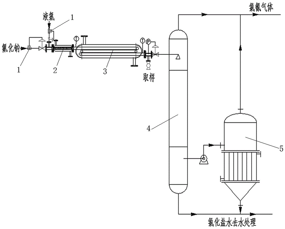
Method for producing cyanogen chloride by using tubular reactor

A tubular reactor, cyanogen chloride technology, applied in chemical instruments and methods, cyanogen halide, cyanide and other directions, can solve the problems of difficult control of gas-liquid mixing effect, strict spray control requirements, short process routes, etc. The effect of investment in fixed assets, simplified reaction equipment, and simple operation

Inactive Publication Date: 2017-02-15
HEBEI LINGANG CHEM
View PDF5 Cites 4 Cited by
  • Summary
  • Abstract
  • Description
  • Claims
  • Application Information

AI Technical Summary

Problems solved by technology

Its advantage is that commercially available sodium cyanide can be prepared into an aqueous solution, and there is no need to adjust the pH value and remove impurities. The operating procedure is short, the operation steps are simple, and the final product can be immediately separated from the reaction mixture. The control requirements are strict, and the gas-liquid mixing effect is difficult to control
"Liaoning Ch...

Method used


Image

  • Method for producing cyanogen chloride by using tubular reactor

Examples


Embodiment 1

[0020] (1) After the flow is precisely adjusted by the intelligent flowmeter, the flow rate of liquid chlorine is controlled at 0.25t / h, and the flow rate of 30% sodium cyanide aqueous solution is controlled at 0.5t / h, respectively pass through their respective liquid feed pumps and enter the mixer for mixing. Control the outlet temperature of the mixer at 30°C, and control the molar ratio of sodium cyanide and liquid chlorine to 1:1.15;

[0021] (2) Introduce the mixed feed liquid into the tubular reactor, control the pressure of the tubular reactor to 0.8MPa, control the reaction temperature at 40°C with circulating water, and the reaction residence time is 30s, and take samples for detection;

[0022] (3) After the reaction is completed, the feed liquid enters the desorption tower from the end of the tubular reactor. The temperature of the desorption tower is controlled at 50°C. After desorption and drying, pure cyanogen chloride gas is obtained, and the conversion rate ...

Embodiment 2

[0024] (1) After the flow is precisely adjusted by the intelligent flowmeter, the flow rate of liquid chlorine is controlled at 0.5t / h, and the flow rate of 30% sodium cyanide aqueous solution is controlled at 1.1t / h, which respectively pass through the respective liquid feed pumps and enter the mixer for mixing. Control the outlet temperature of the mixer at 40°C, and control the molar ratio of sodium cyanide and liquid chlorine to 1:1.045;

[0025] (2) Introduce the mixed feed liquid into the tubular reactor, control the pressure of the tubular reactor to 1.2MPa, control the reaction temperature at 45°C with circulating water, and the reaction residence time is 50s, and take samples for detection;

[0026] (3) After the reaction is completed, the feed liquid enters the desorption tower from the end of the tubular reactor. The temperature of the desorption tower is controlled at 60°C. After desorption and drying, pure cyanogen chloride gas is obtained, and the conversion r...


PUM


Abstract

The invention relates to the technical field of the synthesis of fine chemical intermediates, particularly relates to the technical field of the production of cyanogen chloride, and discloses a method for producing the cyanogen chloride by using a tubular reactor. The method comprises the following steps of mixing liquid chlorine with a sodium cyanide aqueous solution according to the mole ratio of sodium cyanide to the liquid chlorine, which is 1 to (0.9 to 1.2), controlling the temperature of obtained mixed liquor to be 20 to 50 DEG C, afterwards, introducing the mixed liquor into the tubular reactor to react, controlling the pressure of the tubular reactor to be 0.1MPa to 2.0MPa, and controlling reaction temperature to be 20 to 60 DEG C, wherein the residence time of the reaction is 10s to 600s; discharging material liquid after the completion of the reaction into a desorption tower from the tail end of the tubular reactor, and controlling the temperature of the desorption tower to be 20 to 60 DEG C, so as to obtain a pure cyanogen chloride gas through desorption and drying. By using the method provided by the invention, the production efficiency can be improved; the method has the advantages that the production yield is high and further the reactor is simple.

Description

technical field [0001] The invention relates to the technical field of synthesis of fine chemical intermediates, in particular to the technical field of production of cyanogen chloride. Background technique [0002] Cyanogen chloride is an intermediate in the production of cyanuric chloride, mainly used in the production of fine chemical intermediates such as cyanuric chloride, diphenylguanidine, sodium dicyandiamide, and chlorhexidine, among which cyanuric chloride has been widely used in In the field of chemical industry, it is an important raw material for many pesticides, herbicides, reactive dyes and fluorescent whitening agents. At the same time, cyanogen chloride can also be used to produce nitrogen fertilizer synergists, surfactants, accelerators, stabilizers, rubber vulcanization accelerators, polymer foaming agents, resin fixatives, polymerization catalysts, fire retardants, photographic sensitizers, Adhesives, cyanaldehyde resins, reverse osmosis membranes, stabi...

Claims


Application Information

Patent Timeline
IPC IPC(8): C01C3/00
CPCC01C3/004C01P2006/80
Inventor 张辰亮郗凌霄程丽华姚立国李正杰刘素良董浩浩李美美
Owner HEBEI LINGANG CHEM
Why Eureka
Try Eureka