Multi-framing optical imaging device with high temporal-spatial resolution and imaging method

A time-space resolution and optical imaging technology, applied in optics, optical components, high-speed photography, etc., can solve the problems of easy distortion of edge images, small dynamic range, and no popularization and application, etc., and achieve high time resolution effect

Active Publication Date: 2017-02-15
NAT UNIV OF DEFENSE TECH
View PDF10 Cites 15 Cited by
  • Summary
  • Abstract
  • Description
  • Claims
  • Application Information

AI Technical Summary

Problems solved by technology

The scanning framing technology has strict requirements on the scanning circuit and the edge image is easily distorted, so it has not been practically popularized and applied, while the microstrip framing technology is restricted by the electron transit...

Method used


Image

  • Multi-framing optical imaging device with high temporal-spatial resolution and imaging method
  • Multi-framing optical imaging device with high temporal-spatial resolution and imaging method
  • Multi-framing optical imaging device with high temporal-spatial resolution and imaging method

Examples


Embodiment 1

[0037] The multi-framing optical imaging device with high temporal and spatial resolution in this embodiment includes: a femtosecond-level ultrashort pulse laser system, a time delay system, a space shaping system, a time serialization system, a semiconductor detector, a Fourier filter system, a space Framing expansion system, imaging recording system;

[0038] Among them, the femtosecond-level ultrashort pulse laser system is used to generate femtosecond-level ultrashort pulse laser as the light source of the probe light;

[0039] The time delay system controls the recording start moment of the probe light by adjusting the length of the probe light transmission path, so as to achieve high-precision synchronization with the event to be detected.

[0040] Spatial shaping system, used to adjust the spatial distribution of probe light, such as beam diameter and uniformity of beam spatial distribution;

[0041] The order of time delay system and space shaping system can be interc...

Embodiment 2

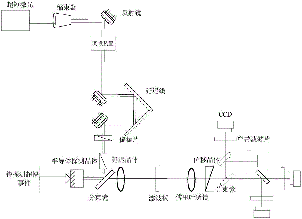
[0052] The imaging method of the multi-framing optical imaging device with high spatio-temporal resolution in this embodiment, as attached figure 1 As shown, the implementation steps are as follows

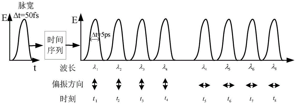
[0053]1) The femtosecond-level ultrashort pulse laser system produces ultrashort laser pulses with a wide spectral width as the probe light. In this embodiment, the ultrafast pulse laser is a titanium sapphire laser with a center wavelength of 800nm, and the half maximum width is 40nm ;

[0054] 2) The time delay system adjusts the probe light transmission length to control the start recording moment of the probe light.

[0055] Figure 5 A time-delay system is shown. The light beam is incident by the mirror M1, transmitted by the mirrors M2 and M3, and then output by the mirror M4. The fixed positions of M1 and M4 remain unchanged, and M2 and M3 are fixed on a movable translation stage, which can move along the left and right at the same time, thereby changing the optical pat...

Embodiment 3

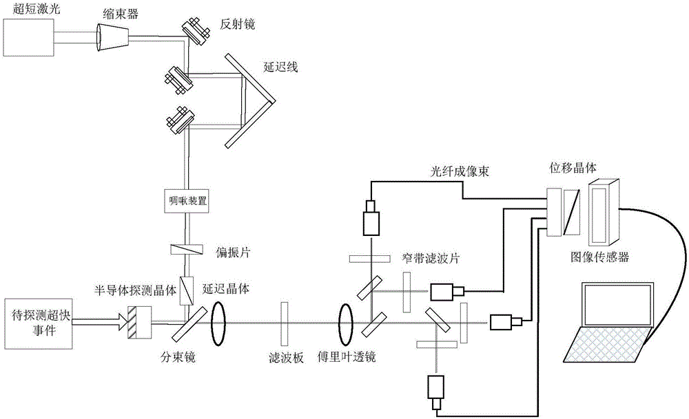
[0065] The imaging method of the multi-framing optical imaging device with high spatio-temporal resolution in this embodiment, as attached figure 2 As shown, the implementation steps are as follows

[0066] 1) The femtosecond-level ultrashort pulse laser system produces ultrashort laser pulses with a wide spectral width as the probe light. In this embodiment, the ultrafast pulse laser is a titanium sapphire laser with a center wavelength of 800nm, and the half maximum width is 40nm ;

[0067] 2) The time delay system adjusts the probe light transmission length to control the start recording moment of the probe light.

[0068] Figure 5 A time-delay system is shown. The light beam is incident by the mirror M1, transmitted by the mirrors M2 and M3, and then output by the mirror M4. The fixed positions of M1 and M4 remain unchanged, and M2 and M3 are fixed on a movable translation stage, which can move along the left and right at the same time, thereby changing the optical p...


PUM


Abstract

The invention discloses a multi-framing optical imaging device with a high temporal-spatial resolution and an imaging method. The device comprises a femtosecond-magnitude ultra-short pulse laser system, a time delay system, a spatial shaping system, a time serialization system, a semiconductor detector, a Fourier filtering system, a spatial framing unfolding system and an imaging recording system, wherein signal light enters the semiconductor detector from a front side; ultra-short pulse laser light is subjected to time delay, spatial shaping and time serialization to form probe light, and the probe light enters the semiconductor detector from a back side; changed image information caused by the signal light is modulated onto serial light pulses of the probe light; and after the modulated probe light is subjected to Fourier filtering and spatial framing unfolding, images at different moments are unfolded spatially and recorded by the imaging recording system. Through adoption of the device, multi-framing imaging with a high temporal resolution and a high spatial resolution can be realized; the spatial resolution is larger than 30lp/mm; the temporal resolution is higher than 5ps; and the framing number is not less than eight images.

Description

technical field [0001] The invention relates to the technical field of high-speed imaging and ultra-fast imaging, in particular to a multi-framing optical imaging device and imaging method with high temporal and spatial resolution. Background technique [0002] Research on ultrafast phenomena is of great significance to research and technical fields such as natural science, energy, materials, biology, photophysics, photochemistry, laser technology, intense light physics, and high-energy physics. Ultrafast imaging technology is an important means for the study of ultrafast phenomena. The time and space resolution index of traditional ultrafast imaging technology is difficult to meet the research needs, which has become the bottleneck of ultrafast phenomenon research. The traditional two-dimensional ultrafast imaging technology is mainly divided into scanning type framing technology and microstrip type framing technology. The scanning framing technology has strict requirement...

Claims


Application Information

Patent Timeline
IPC IPC(8): G03B39/00G02B27/00
CPCG02B27/00G03B39/00
Inventor 陈绍荣贾辉刘希顺张军李修建袁芬芳
Owner NAT UNIV OF DEFENSE TECH
Why Eureka
Try Eureka