Self-driven TiO2 ultraviolet detector and preparation and application thereof
A UV detector, self-driven technology, applied in semiconductor devices, final product manufacturing, sustainable manufacturing/processing, etc., to achieve simple preparation, improve photoresponse efficiency, and reduce recombination
- Summary
- Abstract
- Description
- Claims
- Application Information
AI Technical Summary
Problems solved by technology
Method used
Image
Examples
Embodiment 1
[0030] 1) Place the FTO transparent conductive substrate in acetone, isopropanol, ethanol and deionized water for 20 minutes, and then dry it under air flow;
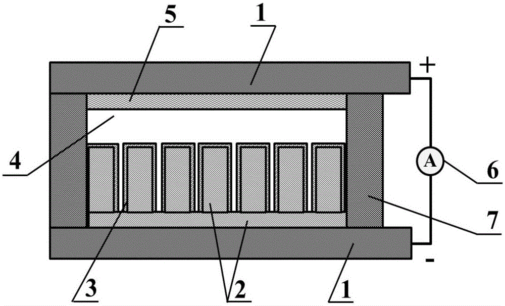
[0031] 2) Place the pre-cleaned FTO transparent conductive substrate (conductive side down) in a polytetrafluoroethylene-lined hydrothermal kettle, add 0.15 mL of tetrabutyl titanate containing HCl and H 2 O volume ratio of 1:1 mixed solution, at 180 ℃ for 2h, grow TiO on the FTO substrate 2 Nanorod array, the nanorod length is about 2μm; XRD results show that the synthesized nanorod array is a pure rutile phase.
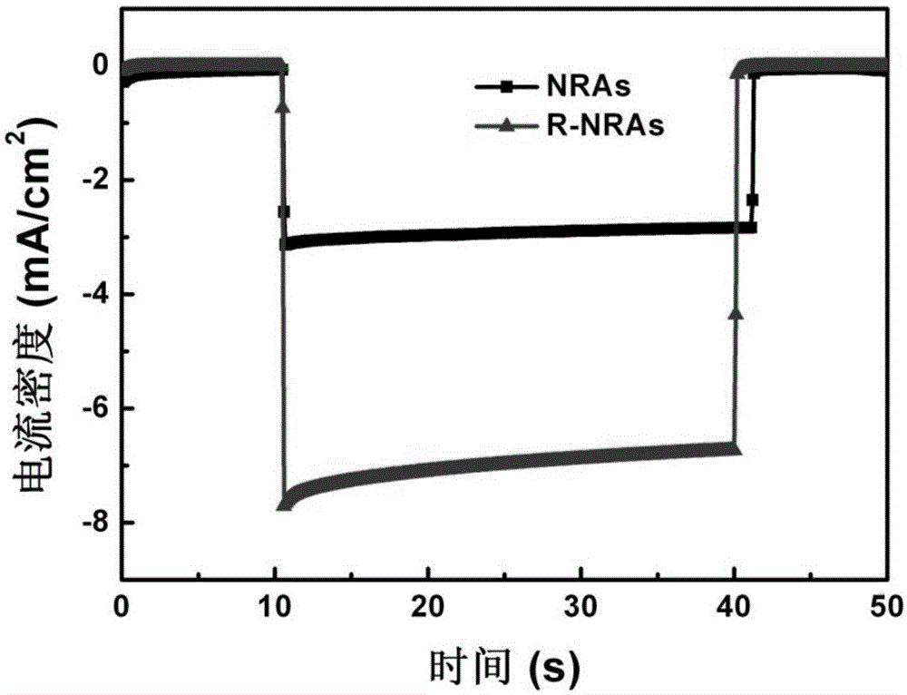
[0032] 3) TiO obtained in step (2) 2 The rutile phase nanorod arrays were placed in a three-electrode electrolytic cell, and TiO 2 Electrode, saturated calomel electrode and Pt electrode are research electrode, reference electrode and counter electrode. Choose a constant voltage of -1.8V, and restore it for 2s;
[0033] 4) Put the clean FTO obtained in step (1) into the magnetron sputtering equipment, use...
Embodiment 2
[0039] 1) Place the FTO transparent conductive substrate in acetone, isopropanol, ethanol and deionized water for 20 minutes, and then dry it under air flow;
[0040] 2) Place the pre-cleaned FTO transparent conductive substrate (conductive side down) in a polytetrafluoroethylene-lined hydrothermal kettle, add 0.15 mL of tetrabutyl titanate containing HCl and H 2O volume ratio of 1:1 mixed solution, at 180 ℃ for 2h, grow TiO on the FTO substrate 2 Nanorod array, the nanorod length is about 2μm; XRD results show that the synthesized nanorod array is a pure rutile phase.
[0041] 3) Put the clean FTO obtained in step (1) into the magnetron sputtering equipment, use the Pt metal target as the target material, and firstly vacuumize the equipment for 10 -5 Pa, and then pass Ar gas into it, adjust the sputtering pressure to 1Pa, and sputter for 1min under the direct current mode of 60W to obtain a layer of Pt conductive electrode, and leave a round hole on it for future use.
[00...
Embodiment 3
[0045] 1) Place the FTO transparent conductive substrate in acetone, isopropanol, ethanol and deionized water for 20 minutes, and then dry it under air flow;
[0046] 2) Place the pre-cleaned FTO transparent conductive substrate (conductive side down) in a polytetrafluoroethylene-lined hydrothermal kettle, add 0.15 mL of tetrabutyl titanate containing HCl and H 2 O volume ratio of 1:1 mixed solution, at 180 ℃ for 2h, grow TiO on the FTO substrate 2 Nanorod array, the nanorod length is about 2μm; XRD results show that the synthesized nanorod array is a pure rutile phase.
[0047] 3) TiO obtained in step (2) 2 The rutile phase nanorod arrays were placed in a three-electrode electrolytic cell, and TiO 2 Electrode, saturated calomel electrode and Pt electrode are research electrode, reference electrode and counter electrode. Choose a constant voltage of -1.6V, and restore it for 2s;
[0048] 4) Put the clean FTO obtained in step (1) into the magnetron sputtering equipment, use...
PUM
 Abstract
Description
Claims
Application Information
 - R&D
- Intellectual Property
- Life Sciences
- Materials
- Tech Scout
- Unparalleled Data Quality
- Higher Quality Content
- 60% Fewer Hallucinations
Browse by: Latest US Patents, China's latest patents, Technical Efficacy Thesaurus, Application Domain, Technology Topic, Popular Technical Reports.
© 2025 PatSnap. All rights reserved.Legal|Privacy policy|Modern Slavery Act Transparency Statement|Sitemap|About US| Contact US: help@patsnap.com


