Negative-pressure cracking system and cracking method

A pyrolysis system and negative pressure technology, applied in the field of pyrolysis system of waste tire rubber particles, can solve the problems of low pyrolysis rate, inconsistent pressure, and high energy consumption, and achieve high recovery rate of pyrolysate, guaranteed effectiveness, and high pyrolysis rate. Effect

Active Publication Date: 2017-02-22
中科钢研节能科技有限公司
View PDF10 Cites 2 Cited by
  • Summary
  • Abstract
  • Description
  • Claims
  • Application Information

AI Technical Summary

Problems solved by technology

At present, many pyrolysis equipment for domestic waste and waste tires cannot be continuously produced, with high energy consumption, low pyrolysis rate and poor safety
[0003] In the existing tire cracking production, it is easier to carry out the cracking reaction by applying negative pressure in the tire cracking link, such as the utilization device introduced in the prior art documents CN02110554A and CN201010183728A to generate a slight negative pressure in the cracking furnace to facilitate, Cracking is achieved better and faster, and there are also methods that use negative pressure to achieve effective transportation in material transportation, such as the prior art document CN201510486609A, but in the prior art, no negative pressure technology is involved in the overall material transportation and cracking process, Moreover, in the existing technology, only a few devices realize negative pressure. Such a setting, in the process of material transportation, due to the inconsistency of the pressure of each device, will be unfavorable to the smooth flow of materials, and may even cause poor material flow under the action of pressure difference. smooth, or even drop, blockage, jamming, etc., resulting in serious adverse consequences
If negative pressure equipment is provided, if it is only to pump air for the cracking furnace, some heat energy will be wasted, which is not in line with the economic principles of industrial production.

Method used


Image

  • Negative-pressure cracking system and cracking method
  • Negative-pressure cracking system and cracking method
  • Negative-pressure cracking system and cracking method

Examples


Embodiment Construction

[0029] The preferred embodiments of the present invention will be described in detail below in conjunction with the accompanying drawings, so that the advantages and features of the present invention can be more easily understood by those skilled in the art, so as to define the protection scope of the present invention more clearly.

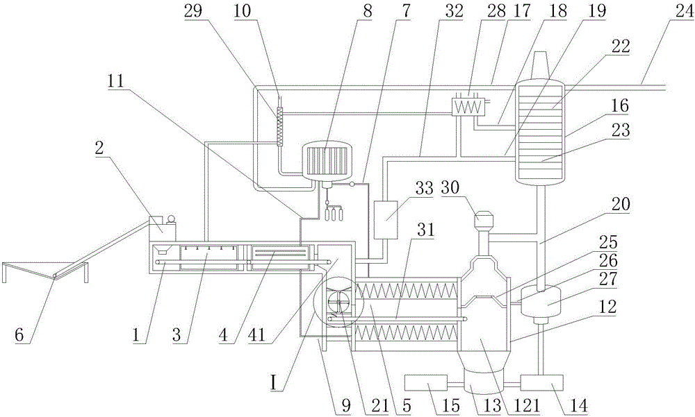
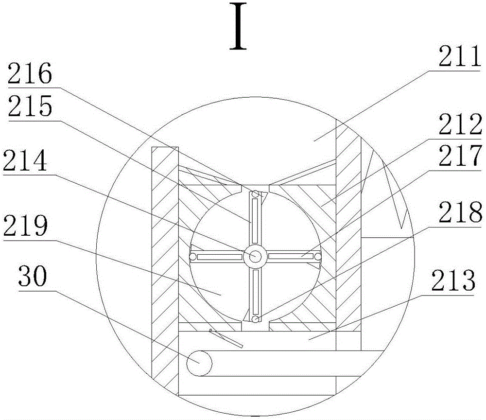
[0030] refer to figure 1 , figure 2As shown, a kind of negative pressure cracking system provided by the present invention comprises a first conveying device 1, which is sequentially connected with a crushing device 2, a washing device 3, a drying device 4, a feeding device 21, and a cracking furnace 5, the crushing device 2 is also connected with the feeding device 6, the cracking furnace 5 is also connected with the gas slag separation device 12, and the gas slag separation device 12 is also connected with the carbon black tank 14 and the steel wire recovery device 15 after passing through the magnetic separation separator 13 , the gas slag s...


PUM


Abstract

The invention discloses a negative-pressure cracking system and a cracking method. The system comprises a conveying device, wherein the conveying device is sequentially connected with a crushing device, a washing device, a drying device, a feeding device and a cracking furnace; a gas-dreg separation device is further connected with a rectifying tower; a dreg material chamber is arranged below the gas-dreg separation device, and an upper part of the gas-dreg separation device is communicated with a gas collection pipe communicated with the rectifying tower; the bottom of the dreg material chamber is communicated with a magnetic separation machine; the feeding device comprises a vertical box body; the vertical box body is composed of a material collection box, a sealed conveying box and a blanking transferring box, which are communicated in sequence from top to bottom; the sealed conveying box is internally provided with a round cavity; a rotary shaft is arranged in the round cavity; a plurality of scraping plates are uniformly mounted on the rotary shaft; the rotary shaft is further connected with a driving device; one end of a second conveying device is arranged in the blanking transferring box and the other end of the second conveying device is arranged in the gas-dreg separation device. In the negative-pressure cracking system and the cracking method, the cracking rate of tire rubber grains is high and the recovery rate of cracked products is high; continuous production can be realized and the energy consumption is low.

Description

technical field [0001] The invention relates to the technical field of tire recycling, in particular to a cracking system for rubber particles of waste tires. Background technique [0002] Plastic and rubber are two widely used synthetic polymer compounds with many superior properties. The environmental pollution caused by their high consumption is becoming more and more serious. How to deal with and utilize these two kinds of waste polymer materials has aroused widespread concern in the world today. At present, many pyrolysis equipment for domestic waste and waste tires cannot be produced continuously, with high energy consumption, low pyrolysis rate and poor safety. [0003] In the existing tire cracking production, it is easier to carry out the cracking reaction by applying negative pressure in the tire cracking link, such as the utilization device introduced in the prior art documents CN02110554A and CN201010183728A to generate a slight negative pressure in the crackin...

Claims


Application Information

Patent Timeline
Patent Type & Authority Applications(China)
IPC IPC(8): C10B53/07C10G1/10
CPCY02P20/143C10B53/07C10G1/002C10G1/10
Inventor 张岩孙涛赵然张斌周亮刘囡南刘波赵方周卫东常彦楠
Owner 中科钢研节能科技有限公司
Why Eureka
Try Eureka