A sprinkler head for mocvd equipment

A spray head and equipment technology, applied in the field of spray head, to achieve the effect of good uniformity of epitaxial growth

Active Publication Date: 2019-04-23
NANCHANG UNIV +1
View PDF4 Cites 0 Cited by
  • Summary
  • Abstract
  • Description
  • Claims
  • Application Information

AI Technical Summary

Problems solved by technology

It can be seen that the above-mentioned mainstream MOCVD reaction chambers have their own advantages and disadvantages, and cannot meet the above requirements at the same time. There is a large room for improvement in terms of improving the utilization rate of metal organic gases and reducing the deposition on the side wall of the reaction chamber.

Method used


Image

  • A sprinkler head for mocvd equipment
  • A sprinkler head for mocvd equipment
  • A sprinkler head for mocvd equipment

Examples


Embodiment 1

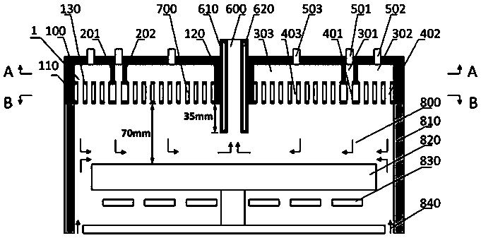
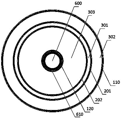
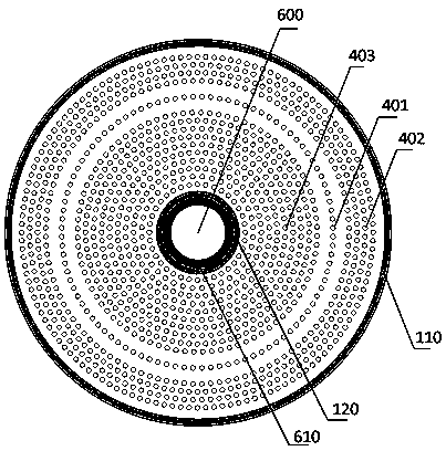
[0031] Such as figure 1 As shown, the present invention provides a shower head for MOCVD equipment, including: an inlet chamber 1 for receiving reaction gases, the inlet chamber 1 is a structure consisting of a top plate 100, an outer sidewall 110, an inner sidewall 120 and a bottom plate 130 constitutes a hollow cylinder, and two vertical circular partition walls 201, 202 are provided in the air inlet chamber 1, and the two circular partition walls 201, 202 divide the air inlet chamber 1 into three mutually isolated inlet chambers. The gas chambers 301, 302 and 303 are respectively provided with corresponding air inlets 501, 502 and 503 on the top plate 100 of the three mutually isolated air inlet chambers 301, 302 and 303 to receive different reaction gases. Corresponding air intake conduits 401, 402, and 403 are respectively arranged on the bottom plate 130 of the mutually isolated air intake chambers 301, 302, and 303, and the air intake conduits 401, 402, and 403 respecti...

Embodiment 2

[0047] Such as Figure 4 with Figure 5 As shown, the structure of embodiment 2 is basically the same as the structure of embodiment 1, the difference is:

[0048] Three vertical circular partition walls 201, 202 and 203 divide the air intake chamber 1 into four annular air intake chambers 301, 302, 303 and 304, and the air intake ducts 401, 304 of the four air intake chambers 402 , 403 and 404 are evenly distributed in the corresponding air intake chambers 301 , 302 , 303 and 304 respectively, and are arranged in a regular single or multiple concentric circles.

[0049] In this embodiment, the four air intake chambers from outside to inside are the air inlet chamber 302 for transporting the second gas, the air intake chamber 301 for transporting the first gas, and the air intake chambers 303 and 304 for transporting the third gas . The first gas is a metal-organic gas, or a mixed gas of a metal-organic gas and a carrier gas; the second gas is a hydride gas, or a mixed gas ...

Embodiment 3

[0057] Such as Image 6 with Figure 7 As shown, the structure of embodiment 3 is basically the same as the structure of embodiment 1, the difference is:

[0058] Two vertical hexagonal partition walls 201 and 202 divide the air intake chamber 1 into three air intake cavities 301, 302 and 303, and the air intake ducts 401, 402 and 403 of the three air intake cavities are respectively in the corresponding The air intake chambers 301, 302 and 303 are evenly distributed in single or multiple circles of a regular hexagon.

[0059] In this embodiment, the three air intake chambers are, from outside to inside, an air intake chamber 302 for transporting the second gas, an air intake chamber 301 for transporting the first gas, and an air intake chamber 303 for transporting the third gas. The first gas is a metal-organic gas, or a mixed gas of a metal-organic gas and a carrier gas; the second gas is a hydride gas, or a mixed gas of a hydride gas and a carrier gas; the third gas is a ...


PUM


Abstract

The invention discloses a spraying head for MOCVD equipment. The spraying head for the MOCVD equipment comprises a plurality of gas inlet chambers which are separated from one another, corresponding gas inlet pipelines, and a tail gas guide pipe which is positioned in the centre of the spraying head. The spraying head is provided with gas inlet guide pipes and the tail gas guide pipe simultaneously; a reaction gas is sprayed into a reaction chamber front top to bottom through the gas inlet guide pipes of the spraying head, and finally, is pumped out from bottom to top through the tail gas guide pipe in the centre of the spraying head; the gas in the reaction chamber flows from the outside to the centre in a radial direction; adverse influence caused by the loss of reactants along a path can be greatly reduced; good epitaxial growth uniformity is beneficially obtained. The gas inlet chambers which are separated from one another can convey a first reaction gas, a second reaction gas or a third reaction gas selectively; by selecting suitable arrangement and combination of the gas inlet chambers, the utilization rate of a metal organic gas can be greatly improved, and reactant deposition on a side wall of the reaction chamber is basically eliminated.

Description

technical field [0001] The invention relates to the technical field of semiconductor manufacturing, in particular to a shower head for MOCVD equipment. Background technique [0002] Metal-organic chemical deposition (MOCVD) technology is an important technical method for growing high-quality compound semiconductor thin film materials. It has significant advantages in the preparation of thin-layer heterojunction, superlattice and quantum well structures, and has become a III-V and The core growth technology of II-VI compound semiconductors and their multiple solid solution materials, especially in the preparation of gallium nitride-based light-emitting diodes and lasers, has achieved great success. [0003] At present, mainstream MOCVD equipment can be divided into horizontal and vertical reaction chambers according to the air flow channel design, among which: [0004] The horizontal reaction chamber design is mainly represented by Aixtron’s planetary reaction chamber, which...

Claims


Application Information

Patent Timeline
Patent Type & Authority Patents(China)
IPC IPC(8): C23C16/455
CPCC23C16/45502C23C16/45565
Inventor 曹盛徐龙权张建立全知觉赵鹏罗磊江风益
Owner NANCHANG UNIV
Why Eureka
Try Eureka