A kind of burner applied in micro-thermal photoelectric system

A micro-thermal photoelectric and burner technology, which is applied in the direction of combustion, combustion type, and combustion method using catalytic materials, can solve the problems of unfavorable energy conversion efficiency of micro-thermal photoelectric system, large temperature difference of outer wall surface, uneven temperature distribution, etc. , to achieve the effect of prolonging the residence time, stabilizing combustion, improving safety and stability

Active Publication Date: 2018-11-09
JIANGSU UNIV
View PDF4 Cites 0 Cited by
  • Summary
  • Abstract
  • Description
  • Claims
  • Application Information

AI Technical Summary

Problems solved by technology

At present, there are many disadvantages in conventional micro-scale combustion chambers, such as large temperature difference on the outer wall surface, uneven temperature distribution, etc., which is not conducive to improving the energy conversion efficiency of micro-thermo-photovoltaic systems.

Method used


Image

  • A kind of burner applied in micro-thermal photoelectric system
  • A kind of burner applied in micro-thermal photoelectric system
  • A kind of burner applied in micro-thermal photoelectric system

Examples


Embodiment Construction

[0029] The present invention will be further described below in conjunction with the accompanying drawings and specific embodiments, but the protection scope of the present invention is not limited thereto.

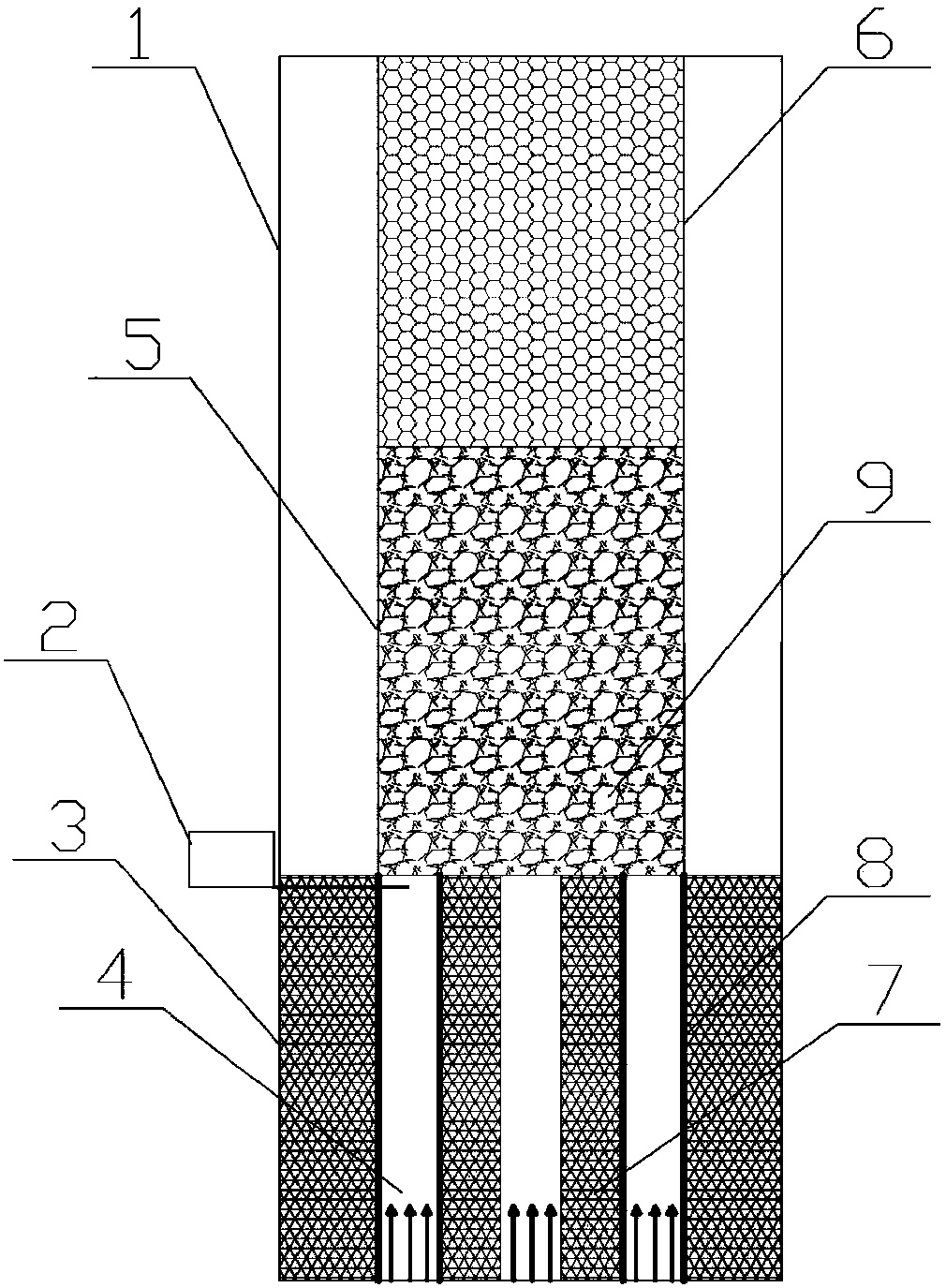
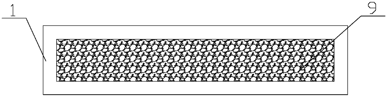
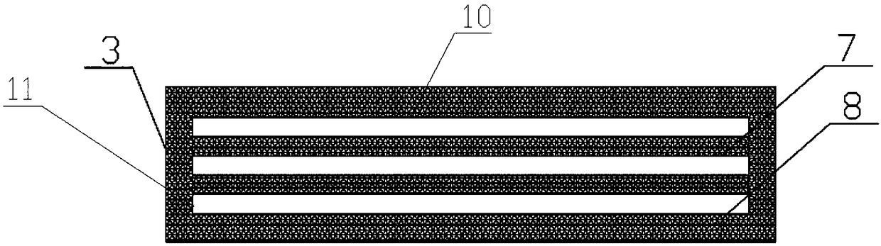
[0030] figure 1 The shown burner applied to the micro-thermal photoelectric system includes an upper part 1 of the combustion chamber, an igniter 2, and a lower part 3 of the combustion chamber; The lower part of the combustion chamber and the upper part of the combustion chamber are made of materials with low thermal conductivity, the lower part of the combustion chamber is made of ceramic material, and the upper part of the combustion chamber is made of high light-transmitting quartz glass; the lower part 3 of the combustion chamber and the upper part 1 of the combustion chamber are cross-sectional It is rectangular; the upper part of the combustion chamber 1 is provided with an exhaust gas treatment area 6 and a porous medium area 5; the filling material in the porous ...


PUM


Abstract

The invention provides a burner applied to a microthermophotovoltaic system. The burner comprises an upper burning chamber portion, an igniter and a lower burning chamber portion; the upper burning chamber portion is adhered with the lower burning chamber portion through a high temperature-resistant adhesive; the cross sections of the upper burning chamber portion and the lower burning chamber portion are rectangular; a tail gas processing area and a porous medium area are arranged in the upper burning chamber portion; the lower burning chamber portion is divided into a plurality of catalytic burning areas by ceramic sheets, one side of the ceramic sheet adjacent to the long edge of the lower burning chamber portion is coated with a catalyst, and the ceramic sheets face the long edge surfaces of the lower burning chamber portion. The igniter is arranged between the upper burning chamber portion and the lower burning chamber portion, and is inserted to the catalytic burning areas. The burner can realize stable and high-efficiency burning of multiple fuels and various limiting conditions in a minimal scale, provides a stable wall surface high temperature, greatly improves the energy utilization rate, and reduces environment pollution.

Description

technical field [0001] The invention relates to the technical field of micro-scale thermal photoelectric energy conversion, in particular to a burner applied to a micro thermal photoelectric system. Background technique [0002] With the increasing demand for micro-electro-mechanical systems and the rapid development of micro-scale processing technology, micro-dynamic mechanical systems have become a current research hotspot. The system is based on the combustion of fuel, and has the characteristics of high energy density (about dozens of times that of conventional lithium batteries) and small size (generally below the millimeter level). As a micro-dynamic mechanical system with no moving parts, the micro-thermal photoelectric system uses the chemical energy released by the combustion of fuel in the burner to convert it into radiant energy on the wall of the burner, and then uses photovoltaic cells to perform photoelectric conversion to generate electrical energy. However, ...

Claims


Application Information

Patent Timeline
Patent Type & Authority Patents(China)
IPC IPC(8): F23C13/00F23C13/08
CPCF23C13/00F23C13/08F23C2900/13001
Inventor 卢青波潘剑锋邵霞陆尧
Owner JIANGSU UNIV
Why Eureka
Try Eureka