Light emitting device, lamp and projection display device

A light-emitting device and wavelength conversion device technology, which is applied in the direction of lighting devices, projection devices, components of lighting devices, etc., can solve problems such as reducing system reliability and limiting system miniaturization

Inactive Publication Date: 2017-03-22
杨毅
View PDF11 Cites 1 Cited by
  • Summary
  • Abstract
  • Description
  • Claims
  • Application Information

AI Technical Summary

Problems solved by technology

However, the use of the turntable reduces the reliability of the system on the one hand, and limits the miniaturization of the system on the other hand.

Method used


Image

  • Light emitting device, lamp and projection display device
  • Light emitting device, lamp and projection display device
  • Light emitting device, lamp and projection display device

Examples


Embodiment Construction

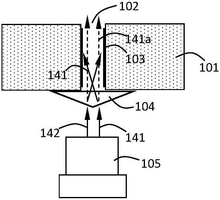
[0018] The present invention proposes a light emitting device, the structural schematic diagram of the first embodiment is as follows Figure 1A shown. The light emitting device includes a wavelength conversion device including a substrate 101 including a hole 102 ; the wavelength conversion device further includes a wavelength conversion layer 103 attached to the inner wall of the hole 102 . The light-emitting device also includes a laser source 105 and a light processing element 104. The laser light emitted by the laser source (take light rays 141 and 142 as an example) is incident on the light processing element 104 and processed by it. The angular distribution of the laser light is in the first angle range, so that the laser light It can all be incident on the wavelength conversion layer 103 on the inner wall of the hole, and the wavelength conversion layer 103 can be excited to emit the converted light.

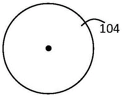
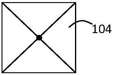
[0019] In this embodiment, the first angle range is as Figure 1D ...


PUM


Abstract

Disclosed are a light emitting device, a lamp and a projection display device. The light emitting device comprises a wavelength conversion device which comprises a perforated substrate and a wavelength conversion layer attached to the inner wall of a hole. The light emitting device also comprises a laser source and a light processing element. A laser emitted from the laser source is incident on the light processing element and processed, and the angular distribution of the laser is in the first angular range, so that the laser can all be incident on the wavelength conversion layer of the inner wall of the hole and the wavelength conversion layer is excited to emit a stimulated laser. The light processing element enables all of the laser to be incident on the wavelength conversion layer of the inner wall of the hole without direct injection from the hole, so that the luminous efficiency and uniformity can be guaranteed. At the same time, the size of the hole limits the size of the aperture of the emitted light, small holes can make the exit light spot become small, and the luminous flux is prevented from being affected, so that relatively higher brightness can be achieved.

Description

[0001] Technical field: [0002] The invention relates to the field of lighting sources, in particular to a light emitting device, a lamp and a projection display device using the light emitting device. [0003] Background technique: [0004] With the development of semiconductor technology, LED light sources are replacing traditional incandescent lamps and energy-saving lamps as a new type of lighting source, which has the advantages of high efficiency, energy saving, environmental protection and long life. However, in some special application fields, such as stage lighting, car headlights, projection display and other fields, what is needed is a light source with ultra-high brightness, and it is difficult for LEDs to meet the requirements at this time. Semiconductor lasers (hereinafter referred to as LD), which belong to the same semiconductor light source as LEDs, also have the advantages of LEDs. At the same time, due to their small etendue, they are especially suitable for...

Claims


Application Information

Patent Timeline
Patent Type & Authority Applications(China)
IPC IPC(8): G03B21/20F21K9/20F21K9/64F21K9/60F21K9/69F21V13/00F21Y115/30
CPCF21K9/00F21V13/00G03B21/204G03B21/208
Inventor 不公告发明人
Owner 杨毅
Why Eureka
Try Eureka