
Laser remote wireless charging device based on visible indication light protection

A wireless charging, long-distance technology, applied in circuit devices, battery circuit devices, current collectors, etc., can solve the problem of no laser transmitter and solar panel specific design, no mutual matching to obtain the best photoelectric conversion efficiency, can not provide high Power and energy and other issues, to overcome the defects of electromagnetic wave principle, fast charging speed and light weight

Inactive Publication Date: 2017-03-29
JINAN UNIVERSITY
View PDF12 Cites 6 Cited by
  • Summary
  • Abstract
  • Description
  • Claims
  • Application Information

AI Technical Summary

Problems solved by technology

"Indoor Automatic Laser Charging System and Method (CN20110097652.0)", "A Wireless Laser Charging Equipment for UAV and Its Charging System (CN201510102715.2)" and so on proposed the realization of laser charging from the aspects of machinery, control, communication, etc. method, but there is no specific design on the use of specific laser emitters and solar panels, let alone a specific implementation of the two matching each other to obtain the best photoelectric conversion efficiency
The space-borne laser wireless energy transmission system (CN201210593990.5) is a solution for the special requirements of the aerospace field. It has a complex alignment system, which is not only expensive, but also complicated to use, requiring high professional requirements for users.
At the same time, there is no relevant component to solve the problem of uneven laser spot in the solution, and it can only be used for laser irradiation of a single photocell, which cannot provide high-power energy

Method used


Image

  • Laser remote wireless charging device based on visible indication light protection

Examples


Embodiment

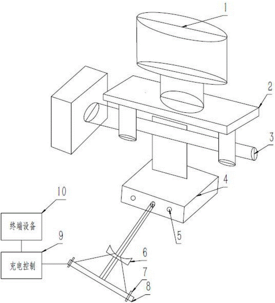
[0034] Such as figure 1 As shown, this embodiment discloses a laser long-distance wireless charging device based on visible indicator light protection. The device uses laser as a carrier, that is, the transmitting end converts electrical energy into laser energy and transmits it to the receiving end, and the receiving end converts the laser for electrical energy. It overcomes the requirements that the microwave transmitting and receiving devices are bulky and not suitable for portable use; and avoids the oscillation frequency matching problem caused by the individual deviation of the inductance and capacitance components and temperature drift in the electromagnetic induction type. The invisible wave band light wave is used as the form of energy transfer, which will not cause light pollution and interference to communication signals. It can not only achieve wireless transmission, but also effectively overcome the defects of the principle of electromagnetic waves, and realize l...


PUM


Abstract

The invention discloses a laser remote wireless charging device based on visible indication light protection. The device forms a solar cell panel by adopting a plurality of photocell panels through serial connection and parallel connection, and thus the phenomenon that the current is limited by photocells with minimum photo-generated current when only the series-connected photocell panels are under non-uniform illumination, and energy loss and 'heat spots' are caused can be solved. By adopting a laser beam adjuster, laser beam divergence angles output by a laser can be optimized and the uniformity of the output laser energy can be increased; and the beam density and wavelengths of a semiconductor laser transmitter or a diode-pumped solid laser transmitter which is adopted are respectively matched with the energy gap width of the photocell panels which are made of GaAs or InGaAs materials, and thus the characteristics of high photoelectric conversion efficiency and low heat loss can be achieved. The device disclosed by the invention is high in charging efficiency, low in energy loss and fast in charging speed, and cannot be limited by the distance; the overall dimension of charging devices is small, and in addition, the optical wave in non-visible bands is adopted as an energy transfer form, and thus the light pollution and the interference to communication signals cannot be generated.

Description

technical field [0001] The invention relates to the technical field of wireless charging, in particular to a laser long-distance wireless charging device based on visible indicator light protection. Background technique [0002] There are many forms of power transmission. At present, the most common is wired transmission. There must be a wire connection between the charger and the electronic device; it can also be carried by a battery, charging in one place and discharging in another; the other is wireless charging. Several wireless charging methods mainly include solar energy, microwave, electromagnetic induction and magnetic resonance. [0003] The solar charging method is affected by weather, season, and angle, and it is difficult to provide a large current output in a small volume, and it is difficult to meet the requirements of fast charging. The microwave divergence is strong, which makes the size of the receiving antenna of the system too large. Electromagnetic indu...

Claims


Application Information

Patent Timeline
IPC IPC(8): H02J50/30H02J7/00
CPCH02J7/0042
Inventor 尹浩李真朱思祁何铁锋李安明付神贺张沛雄陈振强
Owner JINAN UNIVERSITY
Learn More