Boiler denitration process taking ammonia-containing waste gas as denitration agent

A technology for denitrification agent and waste gas, which is applied in the separation of dispersed particles, chemical instruments and methods, separation methods, etc., can solve the problems of reducing the investment of denitrification equipment, reducing the cost of denitrification of boilers, and blocking the tail flue, so as to reduce the consumption of latent heat of vaporization. , good economic and environmental benefits, the effect of reducing heat waste

Active Publication Date: 2017-04-26
JIUTAI ENERGY INNER MONGOLIA
View PDF5 Cites 3 Cited by
  • Summary
  • Abstract
  • Description
  • Claims
  • Application Information

AI Technical Summary

Problems solved by technology

[0005] In the present invention, the ammonia-containing waste gas produced by the gasifier can be used as a boiler denitrification agent after being treated by a specific process, which significantly reduces the cost of boiler denitrification, reduces the investment in denitrification equipment, and can also make the ammonia-containing waste gas resource utilization, reducing Environmental pollution, and at the same time, it can solve the problem that the traditional denitrification technology has a large amount of ammonia escape, which easily leads to the blockage of the tail flue

Method used


Image

  • Boiler denitration process taking ammonia-containing waste gas as denitration agent

Examples


Embodiment 1

[0034] Example 1 A boiler denitrification process using ammonia-containing waste gas as a denitrification agent

[0035] The specific steps of the process are as follows:

[0036] (1) In the gasifier, coal and water react under oxygen-enriched conditions to produce a crude process gas that is mainly process gas and contains ammonia as a by-product. The crude process gas enters the carbon scrubber, and in the carbon scrubber remove solid particles;

[0037] (2) The ammonia-containing crude process gas enters the shift furnace after passing through the carbon washing tower, and part of the carbon monoxide and water vapor in the shift furnace are converted into carbon dioxide and hydrogen under the action of the catalyst, and the side reactant ammonia does not participate in the reaction;

[0038] (3) The crude process gas containing ammonia enters the heat exchange system after passing through the shift furnace, and the temperature is lowered in the heat exchange system. The te...

Embodiment 2

[0050] Example 2 A boiler denitrification process using ammonia-containing waste gas as a denitrification agent

[0051] The specific steps of the process are as follows:

[0052] (1) In the gasifier, coal and water react under oxygen-enriched conditions to produce a crude process gas that is mainly process gas and contains ammonia as a by-product. The crude process gas enters the carbon scrubber, and in the carbon scrubber remove solid particles;

[0053] (2) The ammonia-containing crude process gas enters the shift furnace after passing through the carbon washing tower, and part of the carbon monoxide and water vapor in the shift furnace are converted into carbon dioxide and hydrogen under the action of the catalyst, and the side reactant ammonia does not participate in the reaction;

[0054] (3) The crude process gas containing ammonia enters the heat exchange system after passing through the shift furnace, and the temperature is lowered in the heat exchange system. The te...

Embodiment 3

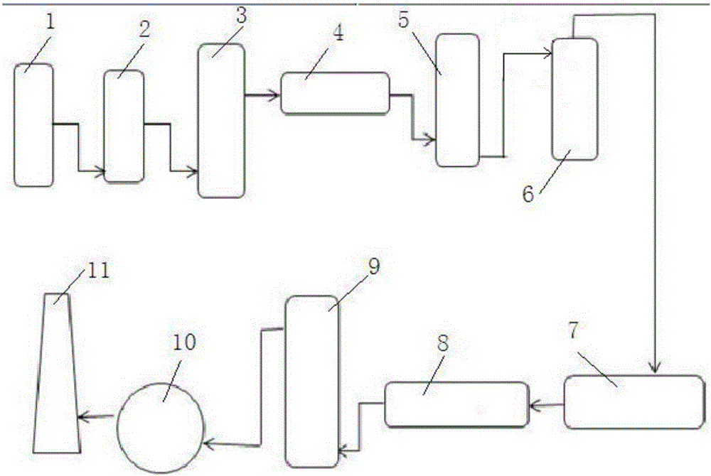
[0067] Example 3 A boiler denitrification system using ammonia-containing waste gas as a denitrification agent, such as figure 1 As shown, the system includes gasification furnace 1, carbon washing tower 2, converter furnace 3, heat exchange system 4, ammonia washing tower 5, stripping tower 6, waste gas mixer 7, boiler air supply system 8, boiler 9, induced draft fan 10 and the chimney 11, the gasifier 1 is connected to the inlet of the carbon scrubber 2 through a pipeline, the outlet of the carbon scrubber 2 is connected to the inlet of the converter 3 through a pipeline, and the outlet of the converter 3 is connected to the inlet of the heat exchange system 4, The outlet of the heat exchange system 4 is connected with the inlet of the ammonia scrubber 5, the ammonia scrubber 5 is provided with a gas outlet and a liquid outlet, the liquid outlet of the ammonia scrubber 5 is connected with the inlet of the stripper 6, and the outlet of the stripper 6 is connected with the The...


PUM


Abstract

The invention relates to a boiler denitration process taking ammonia-containing waste gas as a denitration agent. The boiler denitration process includes the steps: generating raw process gas by a gasification furnace; enabling the raw process gas to enter a carbon washing tower and then enter a conversion furnace; enabling the raw process gas to enter an ammonia washing tower through a heat exchange system; forming ammonia-containing washing water in the ammonia washing tower; enabling the ammonia-containing washing water to enter a stripping tower; forming the ammonia-containing waste gas after stripping in the stripping tower; enabling the ammonia-containing waste gas to enter a waste gas mixer; mixing the ammonia-containing waste gas with secondary air of a boiler; enabling the mixed gas to enter the boiler through a boiler air supply system to perform denitration reaction; exhausting the denitrified boiler waste gas from a chimney through an induced draft fan. The ammonia-containing waste gas serves as the denitration agent, resources are utilized, waste gas emission pollution is decreased, and flue gas denitration cost is remarkably reduced. In the denitration process, compared with traditional SNCR (selective non-catalytic reduction) denitration, the denitration process has the advantages that liquid water vaporization latent heat consumption and heat waste are decreased, and nitric oxide emission concentration is lower than 100mg/m<3>.

Description

technical field [0001] The invention relates to a boiler denitrification process using ammonia-containing waste gas as a denitrification agent, and belongs to the technical field of boiler flue gas denitrification. Background technique [0002] In chemical production, boilers are commonly used to produce water vapor. During combustion in the boiler, coal reacts with oxygen to produce carbon dioxide, which releases heat. During the combustion process, because coal also contains sulfur and nitrogen elements, in addition to producing carbon dioxide, sulfur dioxide and NOx will also be produced. Since NOx is one of the main pollutants in the atmosphere, it is necessary to remove NOx from the boiler flue gas . [0003] Boiler flue gas denitrification technologies mainly include selective catalytic reduction technology (SCR), selective non-catalytic reduction technology (SNCR), mixed SCR+SNCR technology, etc. The traditional SNCR technology generally uses chemical reducing agent...

Claims


Application Information

Patent Timeline
Patent Type & Authority Applications(China)
IPC IPC(8): B01D53/56B01D53/76
CPCB01D53/56B01D53/76B01D2251/2062
Inventor 李先亮邵永飞段永升李翠梅
Owner JIUTAI ENERGY INNER MONGOLIA
Why Eureka
Try Eureka