SCR denitration catalyst evaluation device

A denitrification catalyst and evaluation device technology, which is applied in the field of SCR denitrification catalyst evaluation device, can solve the problems of high test cost, dependence on manual operation, and long time, and achieve unattended automatic operation, easy disassembly and operation, The effect of accurate test results

Inactive Publication Date: 2017-04-26
华纳创新(北京)科技有限公司
View PDF5 Cites 6 Cited by
  • Summary
  • Abstract
  • Description
  • Claims
  • Application Information

AI Technical Summary

Problems solved by technology

[0006] (1) The flue gas flow rate is difficult to adjust accurately
Usually there is only one main flue gas channel, and the flue gas flow can only be roughly adjusted manually through the basic flue gas generating device, and precise adjustment and setting cannot be achieved, which greatly reduces the applicability of the device and also limits the accuracy of the test results. influences
[0007] (2) It is difficult to control the content of flue gas components
Most of the existing devices control the content of the flue gas components by manually adjusting the flow rate of the flue gas components. It also affects the reliability of the test results
[0008] (3) It is difficult to seal the reactor
Due to the large catalyst samples that can be placed in the medium-sized device, in order to facilitate the operation, the reactor is mostly opene

Method used


Image

  • SCR denitration catalyst evaluation device
  • SCR denitration catalyst evaluation device

Examples


Embodiment 1

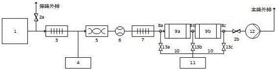
[0035] A kind of SCR denitration catalyst evaluation device of the present invention, flow process is as follows figure 1 shown. The oil-fired boiler (1) is used as the basic flue gas generating device, equipped with two-stage preheaters (3, 7) and two-stage reactors (9). The internal size of each reactor (9a, 9b) is 150*150*1500 mm, the front and rear of the reactor are sealed with graphite gaskets, and the front, middle, and rear are equipped with sampling pipelines (10) and online analysis systems (11 ) connection, the flue gas flow is measured by the flow meter (6), and forms a control loop with the flow regulating valve (2a) on the outlet bypass of the boiler (1) and the flow regulating valve (2b) on the outlet pipeline of the reactor. Reactor flue gas flow.

Embodiment 2

[0037] An SCR catalyst evaluation device of the present invention is different from Embodiment 1 in that a natural gas combustion furnace and a water removal device are used instead of an oil-fired boiler (1).

Embodiment 3

[0039] An SCR catalyst evaluation device of the present invention is different from Embodiment 1 in that the boiler outlet pipeline does not include a flue gas bypass pipe and a regulating valve (2a), and does not have the function of automatically adjusting the flue gas flow.


PUM


Abstract

The invention relates to an SCR denitration catalyst evaluation device, which can evaluate the performance of an SCR denitration catalyst under real conditions. The basic flue gas of the evaluation device is generated by a gas boiler or a fuel boiler. The evaluation device is provided with a gas distribution system and a flue gas mixing device, which can evenly add NO, NH3, SO2, O2, and H2O into the basic flue gas. A two section type pre-heater is provided and is capable of preheating the flue gas to a temperature of 200-550 DEG C. A reactor is arranged after a secondary pre-heater and is composed of 2 to 4 serially connected reaction pipes. The size of the inner cross section of each reaction pipe is 50*50-150*150 mm, and the length of each reaction pipe is 500 to 1500 mm. The work temperature is 200 to 450 DEG C. The evaluation device is provided with a sampling pipeline, which is used to carry out online analysis on the concentrations of components in the flue gas. One end of the sampling pipeline is connected to the sampling ports in the front and rear part of each reaction pipe through switch valves and the other end is connected to an online analysis system. A programmable logic controller is adopted, by controlling a human-computer interaction interface in a computer, a functional element is controlled, and all operation parameters and analysis results are recorded in real time by using database software.

Description

technical field [0001] The invention relates to an evaluation device of an SCR denitration catalyst, in particular to a device capable of evaluating the reaction performance of an SCR flue gas denitration catalyst under real working conditions. Background technique [0002] Nitrogen oxides (NO X ) is one of the most important air pollutants. It can undergo complex secondary chemical reactions with other pollutants in the atmosphere to form acid rain, photochemical smog, and fine particulate matter (PM2.5) that can enter the lungs, seriously affecting environmental quality. , endangering human health. NO in the air X Most of them are produced by the high-temperature combustion process of fossil fuels, and the main sources include thermal power generation, motor vehicle emissions and boiler exhaust gas. China NO in 2013 X Emissions reached 22.274 million tons, of which thermal power generation emissions reached 8.34 million tons, accounting for 37.4% (Analysis of the Curre...

Claims


Application Information

Patent Timeline
IPC IPC(8): G01N31/10G01N35/00
CPCG01N31/10G01N35/00584
Inventor 于海波胡运兴郑小满
Owner 华纳创新(北京)科技有限公司
Why Eureka
Try Eureka