Micro-fluidic chip based on MHD control

A technology of microfluidic chips and microchannels, applied in the field of machinery, can solve the problems of unfavorable integrated development, low sensitivity, and excessive volume, and achieve the effects of convenient integrated development, improved detection efficiency, and low voltage

Inactive Publication Date: 2017-05-10
NANJING UNIV OF POSTS & TELECOMM
View PDF9 Cites 5 Cited by
  • Summary
  • Abstract
  • Description
  • Claims
  • Application Information

AI Technical Summary

Problems solved by technology

This type of low sensitivity, complex structure, and excessive volume are not conducive to the development of integration
Chinese patent application number: 200980120537.9, the device named "analysis device and analysis method using capillary electrophoresis" and Chinese patent application number: 201410355409.5, the chip named "a new type of large-channel electrophoresis microchip" is being implemented The voltages used in the process reach 600V and 1000V respectively. Such high voltages not only affect the activity of the samples to be tested, but also may cause electrochemical reactions, and even pose a threat to the safety of operators.

Method used


Image

  • Micro-fluidic chip based on MHD control
  • Micro-fluidic chip based on MHD control
  • Micro-fluidic chip based on MHD control

Examples


Embodiment 1

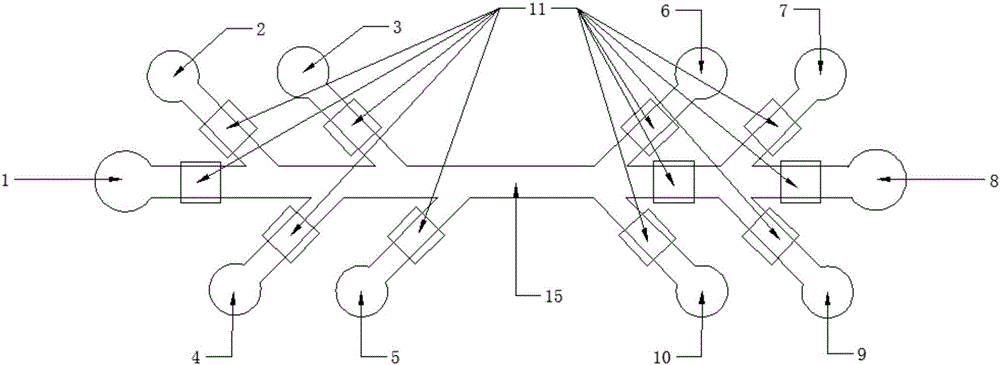
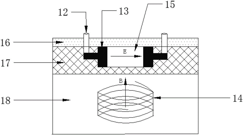
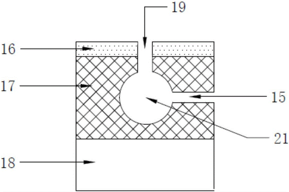
[0026] Such as figure 1 As shown, the present invention provides a microfluidic chip based on MHD control. The microfluidic chip adopts a three-layer structure, and the first layer is a quartz glass sheet 18, such as figure 2 Shown; The second layer is the microchannel layer 17, which is coated with a layer of SU-8 photoresist on the cleaned quartz glass sheet, and after drying, the microchannel 15 is photoetched with an exposure machine. The electrode 13 is electroplated on the channel 15, and the electrode 13 is connected to the electrode connecting column 12. The quartz glass sheet 18 directly below the micro-channel 15 has a groove that can be embedded with a micro-coil 14. The micro-channel layer 17 also includes a liquid storage chamber. 21 and a detection chamber 22; the third layer is the PDMS cover sheet layer 16, on which the outlet of the electrode connection column 12, the injection port 19 and the observation port 20 are left. Specifically include:

[0027] The...

Embodiment 2

[0034] The sample of the liquid storage chamber 2 of the present invention flows to the detection chamber D9: the sample is injected into the liquid storage chamber 2 through the injection port 19, and the adjustment is applied to the liquid storage chamber 2, the liquid storage chamber 3, the liquid storage chamber 4, and the liquid storage chamber 2. The direction of the electric field and the magnetic field of the AC MHD driven pump 11 on the tributaries where the liquid chamber 5, the detection chamber A6, the detection chamber B7, and the detection chamber E10 are located, the direction of the Lorentz force that the sample receives under the action of the electromagnetic field points to the main channel; and the sample The Lorentz force received by the AC MHD driven pump 11 flowing through the tributary where the detection chamber D9 is located points to the detection chamber D9; adjust the direction of the electric field and magnetic field of the AC MHD driven pump 11 clos...

Embodiment 3

[0036] The sample of the liquid storage chamber-1 of the present invention is mixed with the reagent of the liquid storage chamber three 3 and the reagent of the liquid storage chamber four 4 and flows to the detection chamber A6 and the detection chamber E10: the sample is injected into the liquid storage chamber-1 through the injection port 19, and the sample is injected into the liquid storage chamber-1. Reagent is injected into liquid storage chamber three 3 , and reagent is injected into liquid storage chamber four 4 . Adjust the direction of the electric field and the magnetic field of the AC MHD driven pump 11 applied to the tributaries where the liquid storage chamber 2, liquid storage chamber 3, liquid storage chamber 4, and liquid storage chamber 5 are located, so that the Loren The direction of the force points to the main channel; adjust the direction of the electric field and the magnetic field of the AC MHD drive pump 11 close to the liquid storage chamber 1, so t...


PUM


Abstract

The invention discloses a micro-fluidic chip based on MHD control. The micro-fluidic chip is invented based on Ac MHD driving technology; a three layer structure is adopted; the first layer is a PDMS cover plate layer 16, is provided with electrode connection columns 12, an injection port 19, and an observing port 20 hole; the second layer is micro-channel layer 17 comprising an Ac MHD driving pump 11, a micro channel 15, a liquid storage chamber 21, and a detection chamber 22, wherein the Ac MHD driving pump 11 comprises the electrode connection columns 12, electrodes 13, and a micro solenoid coil 14 right below a micro channel 15; the third layer is quartz glass slice 18 provided with a groove via caving, and the groove is used for accommodating the micro solenoid coil 14. In applications, samples or reagents are injected into different liquid storage chambers 21, and flow into a preset detection chamber 22 for analysis under the control of Ac MHD driving pump, multipath simultaneous detection can be realized, detection efficiency is increased, and the micro-fluidic chip possesses practical application value.

Description

technical field [0001] The invention relates to a microfluidic control chip based on MHD control, which belongs to the field of mechanical technology. Background technique [0002] Microfluidic chip technology integrates the basic operation units of sample preparation, reaction, separation, and detection in the process of biological, chemical, and medical analysis into a micron-scale chip to complete the entire analysis process. The analysis and detection of samples on a micron-level chip only requires microliter or even nanoliter samples and reagents, and its cost is greatly reduced compared with high-throughput analysis systems. conditions of. Most of the microfluidic chips currently on the market can only analyze and detect a single sample, using a mechanical drive method, which has low sensitivity and is too large to be conducive to the development of integration. [0003] Chinese patent application number: 201510191236.2, titled "Nucleic acid automatic extraction micr...

Claims


Application Information

Patent Timeline
Patent Type & Authority Applications(China)
IPC IPC(8): B01L3/00
CPCB01L3/502707B01L3/50273B01L2200/10B01L2300/0887B01L2400/0415B01L2400/043
Inventor 万静姜桂荣薛凤兰胡芳仁
Owner NANJING UNIV OF POSTS & TELECOMM
Why Eureka
Try Eureka