
Low-temperature drying device for sludge

A sludge drying and sludge technology, applied in the direction of dewatering/drying/concentrating sludge treatment, can solve the problems of insufficiency of equipment, secondary pollution of exhaust gas, large energy consumption of evaporation, etc. Large contact area and improved drying effect

Active Publication Date: 2017-05-10
四川天润德环境工程有限公司
View PDF5 Cites 16 Cited by
  • Summary
  • Abstract
  • Description
  • Claims
  • Application Information

AI Technical Summary

Problems solved by technology

[0005] High energy consumption: most processes need to heat the water to 100°C, the energy consumption of evaporation is large, and the energy utilization rate is low
[0006] Causes secondary pollution: The traditional process has the problem of secondary pollution caused by tail gas emissions during the drying process, and the odor needs to be collected and treated, which increases the treatment cost
[0007] Poor safety: The traditional sludge drying process has certain potential safety hazards due to the generation of dust and the high temperature of the working environment
[0008] Unsatisfactory drying effect: due to the high viscosity of sludge, effective pretreatment must be carried out before drying. Most of the equipment on the market currently uses orifice extrusion technology for pretreatment, but this technology is less affected by mud Large, the molding effect is not good, resulting in poor air permeability of the sludge and unsatisfactory drying effect
[0009] The equipment occupies a large area: most of the equipment currently on the market is separated from the drying system and the heat pump system, so the equipment is not compact enough and occupies a large area

Method used


Image

  • Low-temperature drying device for sludge
  • Low-temperature drying device for sludge
  • Low-temperature drying device for sludge

Examples


Embodiment Construction

[0039] The present invention is specifically described below by way of embodiment, and present embodiment is only used to further illustrate the present invention, but can not be interpreted as the restriction to protection scope of the present invention, some non-compliances that those skilled in the art make according to the content of the present invention above-mentioned Essential improvements and adjustments also belong to the protection scope of the present invention.

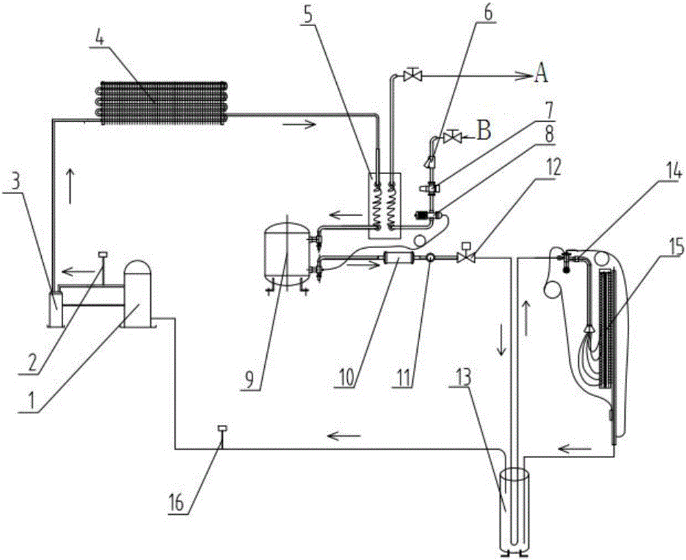
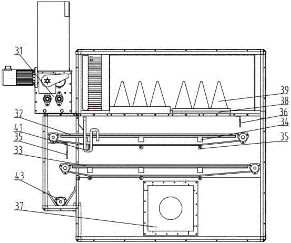
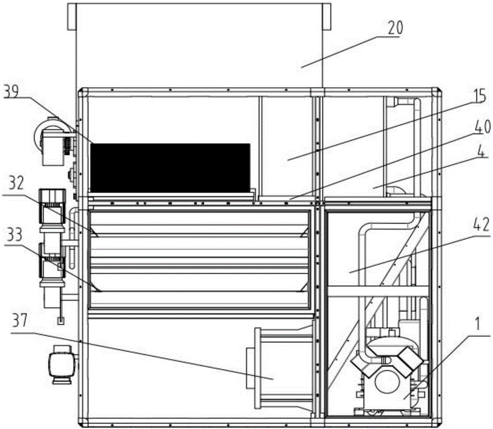
[0040] combine Figure 1 to Figure 7 .

[0041]As shown in the figure, the sludge low-temperature drying device includes a sludge forming distributing machine 31, a sludge drying chamber containing two layers of conveying mesh belts, a heat pump system, a dry and hot air generating chamber, a fan 37 and a set at the sludge outlet. The sludge discharge screw 43; the sludge forming distributing machine 31 is arranged outside the sludge drying chamber and above the beginning end of the first conveying mesh ...


PUM


Abstract

The invention discloses a low-temperature drying device for sludge. The low-temperature drying device comprises a sludge running system and a heated dry air running system, wherein the sludge running system consists of a totally enclosed sludge drying chamber; the sludge drying chamber comprises a sludge inlet, multiple layers of conveying mesh belts which are jointed end to end and a sludge outlet, which are arranged from top to bottom; the heated dry air running system consists of a heat pump system, a heated dry air generating chamber and a fan, and forms a circulating drying air current which is from bottom to top in the sludge drying chamber. According to the low-temperature drying device, the sludge drying chamber, the heated dry air generating chamber, the fan and a discharge screw conveyer are all in one totally enclosed box body; the escape of a smell is avoided; the secondary pollution is not caused to the environment; the effective disintegration and molding are carried out on the sludge, which is not dried, through a molding spreader; strip sludge which does not mutually adhere and is good in air permeability is formed; the drying effect on the sludge is greatly promoted; the safe reliability of an appliance is ensured through a drying condition of a lower temperature; the low-temperature drying device has the advantages of being low in energy consumption, good in effect, safe, reliable, free from the secondary pollution, wide in scope of application and long in service life.

Description

technical field [0001] The invention belongs to the technical field of environmental protection equipment design, in particular to the technical field of sludge treatment equipment design in the urban sewage treatment process, and specifically relates to a low-temperature sludge drying device for dehumidifying and drying the sludge generated in the sewage treatment process. Background technique [0002] The sludge produced by my country's urban sewage treatment plants is difficult to be used as a resource due to its high water content, high viscosity, bacteria, pathogens, etc., and it can be used for composting or incineration after proper drying treatment. Sludge reduction saves sludge disposal costs and transportation costs, and the thermal drying technology in the drying technology has the unique advantages of small footprint, high drying efficiency, and little pollution to the environment. [0003] Commonly used thermal drying technologies include paddle-type drying proce...

Claims


Application Information

Patent Timeline
IPC IPC(8): C02F11/12
CPCC02F11/12
Inventor 王彬张进
Owner 四川天润德环境工程有限公司
Learn More