Surface thermal insulation structure of high temperature device

A high-temperature device and insulation layer technology, which is applied in the direction of heat preservation, pipeline protection, and pipeline protection through heat insulation, can solve the problems of poor compatibility between thermal insulation materials and the surface size of high-temperature devices, poor thermal insulation and waterproof performance, and high surface temperature. Achieve excellent heat insulation ability, reduce thickness, and good thermal insulation integrity

Active Publication Date: 2017-05-10
JIANGSU DEWEI ENERGY SAVING CO LTD
View PDF1 Cites 3 Cited by
  • Summary
  • Abstract
  • Description
  • Claims
  • Application Information

AI Technical Summary

Problems solved by technology

[0004] When high-temperature devices such as steam turbines are working, they are in a high-temperature state inside. In order to ensure the normal operation and operation safety of high-temperature devices, it is necessary to insulate the surface of high-temperature devices. After the cloth is fixed, the surface is coated with asphalt or wrapped with iron sheets, but this method does not have a good size fit between the thermal insulation material and the surface of the high-temperature device, the bonding force is weak, and there are large gaps, and the thermal insulation and waterproof performance is poor.
Later, a method of splicing multiple insulation blocks to form an overall insulation layer was developed. As described in Chinese patent 201220334056.7, this method has significantly improved the size matching with the surface of the steam turbine compared with the traditional method, but there are still many seams and installation problems. Complexity, poor overall strength, and high surface temperature

Method used


Image

  • Surface thermal insulation structure of high temperature device
  • Surface thermal insulation structure of high temperature device

Examples


Embodiment Construction

[0023] The present invention will be described in detail below in conjunction with the accompanying drawings and specific embodiments, wherein the schematic embodiments and descriptions are only used to explain the present invention, but are not intended to limit the present invention.

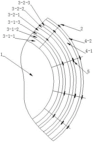
[0024] like figure 1 As shown, the present invention takes a steam turbine shell as an example, first welding a number of insulation nails 2 on the steam turbine casing main body 1, and then laying an inner insulation layer 3, which is composed of one or more sets of composite material insulation structures. Adopted two groups of composite material insulation structures in the example, first make the sprayed ceramic fiber layer-3-1-1 in the first group of insulation structures, then lay the nanoporous airgel insulation layer-3-1 in the first group of insulation structures 1-2, the nanoporous airgel insulation layer 1-3-1-2 adopts two layers of nano-silica airgel insulation blanket in this embo...


PUM


Abstract

The invention relates to a surface thermal insulation structure of a high temperature device. The surface thermal insulation structure is particularly applicable to surface thermal insulation of a steam turbine. The surface thermal insulation structure comprises insulation pins welded on the surface of the high temperature device and an internal thermal insulation layer formed by at least one group of composite thermal insulation structures; the internal thermal insulation layer comprises a spraying ceramic fiber layer, a nano hole aerogel thermal insulation layer and a steel wire mesh layer from inside to outside; the spraying ceramic fiber layer is formed by spraying ceramic fiber mixed with a high temperature resistant binding agent, and can be firmly absorbed to the surface of the high temperature device, and the influence from the surface unevenness of the high temperature device and a phenomenon that the root of a connecting pipe can not be applied with cut thermal insulation cotton in place easily are eliminated. The surface thermal insulation structure is simple in structure and reasonable in design, and has the advantages that the thermal insulation integrity is good, the connection is firm, the required insulation thickness is low, the construction is easy, the surface thermal insulation structure is free from the influence from the surface unevenness, and the construction of a special-shape part is facilitated.

Description

[0001] 【Technical field】 [0002] The invention relates to a surface heat preservation structure of a high temperature device, and is especially suitable for the technical field of heat preservation of steam turbines. [0003] 【Background technique】 [0004] When high-temperature devices such as steam turbines are working, they are in a high-temperature state inside. In order to ensure the normal operation and operation safety of high-temperature devices, it is necessary to insulate the surface of high-temperature devices. After the cloth is fixed, the surface is coated with asphalt or wrapped with iron sheets, but the thermal insulation material has poor size compatibility with the surface of the high-temperature device, weak bonding force, large gaps, and poor thermal insulation and waterproof performance. Later, a method of splicing multiple insulation blocks to form an overall insulation layer was developed. As described in Chinese patent 201220334056.7, this method has sig...

Claims


Application Information

Patent Timeline
Patent Type & Authority Applications(China)
IPC IPC(8): F01D25/14F16L59/12
CPCF01D25/14F16L59/12
Inventor 黄树鸿钊文科嵇国军
Owner JIANGSU DEWEI ENERGY SAVING CO LTD
Why Eureka
Try Eureka