Air separation pre-cooling system

A pre-cooling and air separation technology, applied in refrigeration and liquefaction, liquefaction, solidification, etc., can solve the problems affecting the long-term, safe and stable operation of the air separation unit, the reduction of the working efficiency of the air separation pre-cooling system, and the high temperature of the air at the outlet of the air cooling tower. problems, to achieve the effect of reducing operating costs and maintenance costs, reducing the amount of low-temperature scaling, and reducing the number of shutdowns

Inactive Publication Date: 2017-05-10
HENAN JINKAI CHEM INVESTMENT HLDG GRP
View PDF3 Cites 5 Cited by
  • Summary
  • Abstract
  • Description
  • Claims
  • Application Information

AI Technical Summary

Problems solved by technology

Normal temperature water enters the lower part of the air-cooling tower 30 under the action of the pump 29. The low-temperature water in the pre-cooling system of the air separation unit usually uses circulating water. , to cool down the air, the circulating water contains calcium and magnesium ions, long-term operation is easy to produce low-temperature crystals, and it is easy to form low-temperature scaling in the ammonia cooler and block the channel, which will cause the ammonia cooler to fail to work and the air separation pre-cooling effect Not good, the working efficiency of the air separation pre-cooling system is reduced, and the air temperature at the outlet of the air cooling tower is high, which affects the long-term, safe and stable operation of the air separation unit, and can easily cause system shutdown

Method used


Image

  • Air separation pre-cooling system
  • Air separation pre-cooling system
  • Air separation pre-cooling system

Examples


Embodiment Construction

[0021] The present invention will be described in detail below in conjunction with the drawings.

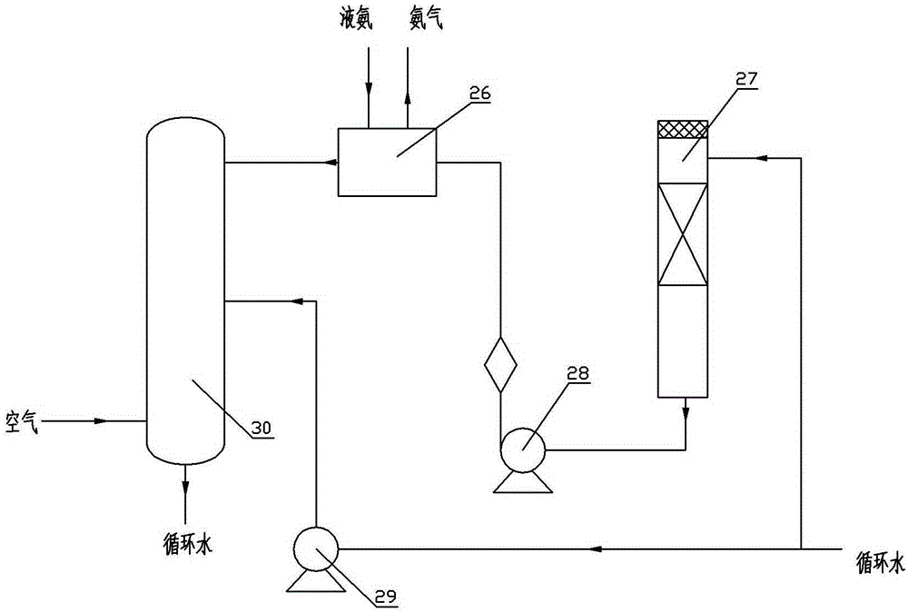
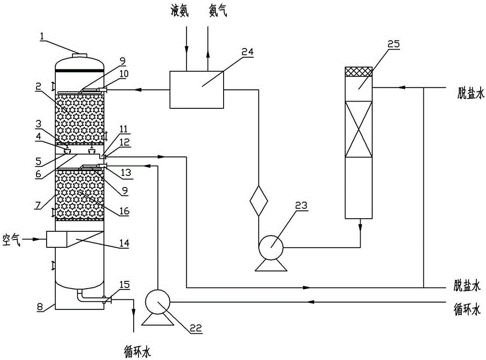
[0022] An air separation pre-cooling system, its structure is as figure 2 As shown, it includes a nitrogen water tower 25, a first pump 23 connected to the bottom of the nitrogen water tower 25, and an ammonia cooler 24 connected to the first pump 23. A double-layer air cooling tower is connected to the ammonia cooler 24.

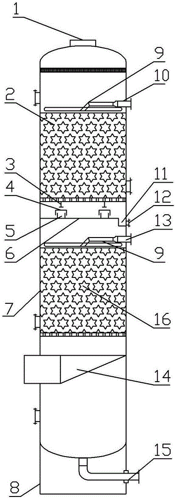
[0023] Such as image 3 As shown, the double-layer air-cooling tower includes a tower body 7, a skirt 8 is provided below the tower body, an air outlet 1 is provided at the top of the tower body 7, an air inlet 14 is provided at the lower part of the tower body 7, and water is provided at the bottom of the tower body 1. At the outlet 15, a partition 6 is arranged in the middle of the tower body 7. The partition 6 divides the space in the tower into an upper cooling tower 2 and a lower pre-cooling tower 16. The partition 6 is provided with an upwardly protruding and...


PUM


Abstract

The invention discloses an air separation pre-cooling system and belongs to the field of gas separation. The air separation pre-cooling system comprises a nitrogen water tower, a first pump connected to the bottom of the nitrogen water tower and an ammonia cooling device connected to the first pump. A double-layer air cooling tower is connected to the ammonia cooling device. The double-layer air cooling tower is divided into an upper-layer cooling tower body and a lower-layer pre-cooling tower body. The top of a tower body of the double-layer air cooling tower is provided with an air outlet. The lower portion of the tower body is provided with an air inlet. A desalted water inlet formed in the upper portion of the upper-layer cooling tower body is connected with the ammonia cooling device. A partition plate is arranged between the upper-layer cooling tower body and the lower-layer pre-cooling tower body. The lower portion of the upper-layer cooling tower body is provided with a desalted water outlet. The side wall of the upper portion of the lower-layer pre-cooling tower body is provided with a circulating water inlet. The bottom of the lower-layer pre-cooling tower body is provided with a water discharging opening. The circulating water inlet is connected with a second pump. The desalted water inlet and the circulating water inlet are connected with a water spraying device arranged in the tower body.

Description

Technical field [0001] The invention belongs to the field of gas separation, and specifically relates to an air separation precooling system. Background technique [0002] At present, the air separation unit adopts a full low pressure, turbine expansion, nitrogen water pre-cooling, molecular sieve adsorption, and internal compression process. The specific process is: compressed air from an air compressor, after being cooled by a pre-cooling system, to the molecular sieve to remove water Servings, SO 2 , SO 3 , NH 3 After waiting for impurities, part of the air is directly sent to the upper tower of the rectification tower, and the other part is sent to the lower tower after entering the expander for expansion and cooling. According to the different boiling points of oxygen, nitrogen and argon components, oxygen, nitrogen and argon products are separated. [0003] The pre-cooling system plays an important role in the air separation unit. The process organization of the pre-coolin...

Claims


Application Information

Patent Timeline
Patent Type & Authority Applications(China)
IPC IPC(8): F25J3/04
Inventor 徐俊红孙嫩霞
Owner HENAN JINKAI CHEM INVESTMENT HLDG GRP
Why Eureka
Try Eureka