Gas blasting machine convenient to inflate
A blaster and gas technology, applied in the field of blasters, can solve problems such as combustion or explosion, complicated process, and low heat release efficiency
- Summary
- Abstract
- Description
- Claims
- Application Information
AI Technical Summary
Problems solved by technology
Method used
Image
Examples
Embodiment 1
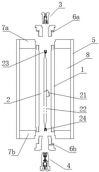
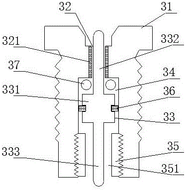
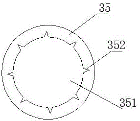
[0099] Such as figure 1 As shown, a gas blaster that is easy to inflate includes an inner tube 1, an inner tube filling cavity 2, a first inflatable conductive head 3, a second inflatable conductive head 4 and an outer tube 5, and the inner tube 1 is an inner tube Filling the chamber 2, the two ends of the inner tube 1 are respectively sealed with a first sealing inner cover 6a and a second sealing inner cover 6b, the outer layer of the inner tube 1 is the outer tube 5, and the inner tube 1 and the outer tube 5 are connected with a second sealing inner cover 6a. A sealing outer cover 7a and a second sealing outer cover 7b; the inner tube 1 is in clearance fit with the first sealing outer cover 7a and the second sealing outer cover 7b, and the outer tube 5 is connected with the first sealing outer cover 7a and the second sealing outer cover 7b sealed connection;
[0100] The first gas-filled conductive head 3 and the second gas-filled conductive head 4 are respectively install...
Embodiment 2
[0119] The difference with embodiment 1 is: as Figure 7 As shown, the inner tube 1 is a composite layer tube containing fiber material, and the inner tube 1 includes: a matrix layer 101, a fiber layer 102, and a hardened layer 103 from the inside to the outside; one end of the inner tube 1 is sealed. Wrapped with a first metal joint 111, the other end of the inner tube 1 is sealed and wrapped with a second metal joint 112, the first metal joint 111 is connected to the first sealed inner cover 6a, and the second metal joint 112 is connected to the second sealed inner cover 6b; Bottoms of the first metal joint 111 and the second metal joint 112 protrude outward to avoid falling off from the inner tube 1 .
[0120] As a further description of the above embodiment, the base layer 101 is made of polyethylene (PE); the fiber layer 102 is made of glass fiber; the hardened layer 103 is made of epoxy resin.
[0121] As a further description of the above embodiment, the implementation...
Embodiment 3
[0125] The difference with embodiment 1 is: as Figure 8 As shown, the outer tube 5 is a composite tube containing fiber material, the outer tube 5 includes an outer tube sealing base layer 501 and an outer tube fiber layer 502 distributed inside and outside, one end of the outer tube 5 is connected with a first winding joint 511, the outer tube 5 The other end of the pipe 5 is connected with a second winding joint 512;
[0126] The top of the outer wall of the first winding joint 511 is provided with a first hanger 5111 for winding fibers, and the top of the outer wall of the second winding joint 512 is provided with a second hanger 5121 for winding fibers. The bottom of the outer wall is provided with a first boss 5112 for connecting the outer tube sealing base 501 , and the bottom of the outer wall of the second winding joint 512 is provided with a second boss 5122 for connecting the outer tube sealing base 501 .
PUM
| Property | Measurement | Unit |
|---|---|---|
| Tensile strength | aaaaa | aaaaa |
| Tensile strength | aaaaa | aaaaa |
| Tensile strength | aaaaa | aaaaa |
Abstract
Description
Claims
Application Information
 - R&D
- Intellectual Property
- Life Sciences
- Materials
- Tech Scout
- Unparalleled Data Quality
- Higher Quality Content
- 60% Fewer Hallucinations
Browse by: Latest US Patents, China's latest patents, Technical Efficacy Thesaurus, Application Domain, Technology Topic, Popular Technical Reports.
© 2025 PatSnap. All rights reserved.Legal|Privacy policy|Modern Slavery Act Transparency Statement|Sitemap|About US| Contact US: help@patsnap.com


