Space stacking light beam distributed phase delayer and speckle elimination method thereof

A phase retarder, stacking technology, applied in optics, instruments, optical components, etc., can solve the problems of high manufacturing cost and large structure, and achieve the effects of low cost, simple device structure and convenient assembly.

Inactive Publication Date: 2017-05-10
SHANXI UNIV
5 Cites 9 Cited by

AI-Extracted Technical Summary

Problems solved by technology

[0004] The purpose of the present invention is to overcome the shortcomings of the prior art, provide a space-stacked beam distributed phase retarder and its s...

Abstract

The present invention relates to a space stacking light beam distributed phase delayer and a speckle elimination method thereof, and relates to the light beam regulation and control dissipated speckle technology. The problems are solved that the structure of the current device of inhibiting laser speckles is large, and the manufacturing cost is high. Polymer micromachining elements or machining transmitting elements are employed, the structure of each polymer micromachining element is an m*n matrix formed by the polymer micromachining element having a certain height difference; the structure of each machining transmitting element is formed by assembling the machining transmitting elements having a certain height difference and having the refractive index being not equal to the air refractive index; the height difference of the polymer micromachining elements or the machining transmitting elements is randomly arranged and satisfies that the optical path difference is larger than or equal to the coherent length LC and the laser coherence is destroyed in the time; and the arrangement of the number of the elements, the length and the arrangement mode is that: a single-beam laser is divided into a plurality of non-coherent illumination light sources, and satisfies that the areas of the non-coherent illumination light sources are larger than or equal to the coherent area AC, and the laser coherence is destroyed in the space.

Application Domain

Technology Topic

Image

  • Space stacking light beam distributed phase delayer and speckle elimination method thereof
  • Space stacking light beam distributed phase delayer and speckle elimination method thereof
  • Space stacking light beam distributed phase delayer and speckle elimination method thereof

Examples

  • Experimental program(2)

Example Embodiment

[0017] Example 1
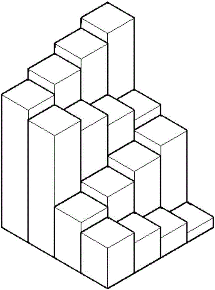
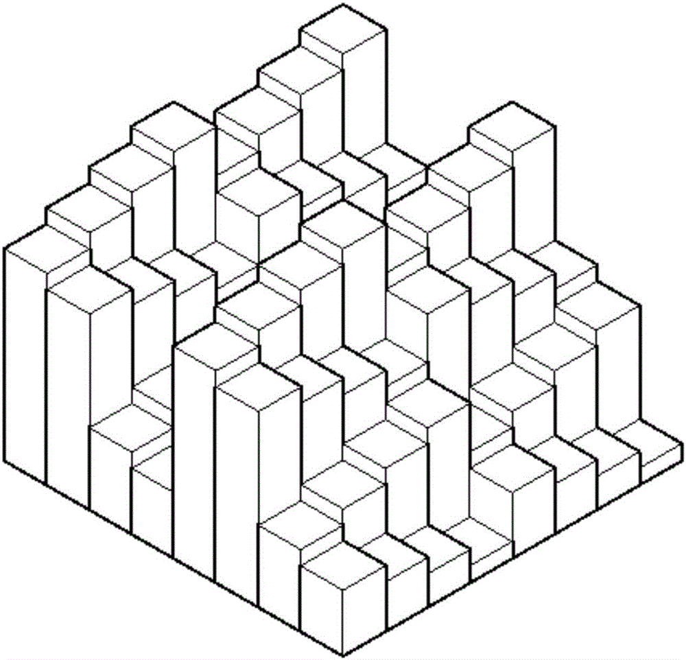
[0018] Such as figure 1 , 2 As shown, a two-dimensional spatially stacked beam distributed phase retarder, wherein: the spatially stacked beam distributed phase retarder is a polymer micromachined element. Take the SU8 photoresist micromachining element as an example, its structure is: an m×n matrix composed of SU8 photoresist micromachining elements with a certain height difference (see figure 1 ), in this embodiment m=n=4, the polymer micro-machining element itself is a two-dimensional phase modulator, which can directly realize the phase modulation of the two-dimensional spatial distribution. The two-dimensional polymer micro-machined element repeats 2×2 times the speckle elimination device (see figure 2 ), it becomes an 8×8 matrix.
[0019] A method for eliminating speckles using a two-dimensional spatially stacked beam distributed phase retarder, the steps of which are: expanding the laser beam emitted by the laser light source through a 4×4 polymer micro-processing element with different height differences. Matrix, the light beam produces optical path difference inside each polymer micro-processing material element, when the optical path difference is greater than or equal to the coherence length L of the laser C When, each light beam passing through the light-transmitting element produces a certain delay in time, which destroys the coherence of the laser and suppresses the laser speckle; the number, length and arrangement of the polymer micro-machining elements are set as needed (see figure 1 , 2 ), where the area of ​​a single unit of the m×n matrix is ​​greater than or equal to the coherence area A C. The laser beam emitted by the laser light source is expanded, and the single coherent laser beam is divided into 16 incoherent independent light sources (see figure 1 ), destroying the coherence of the laser spatially, and reducing the speckle contrast
[0020] It should be noted that the arrangement of heights can be from low to high (see figure 1 , 2 ), it can go from high to low, or from low to high and then lower, or even arrange randomly at will. Requirements: The optical path difference generated by the light beam through the micro-machined polymer element is greater than or equal to the coherence length L C , The area of ​​a single incoherent illumination source is greater than or equal to the coherent area A C.

Example Embodiment

[0021] Example 2
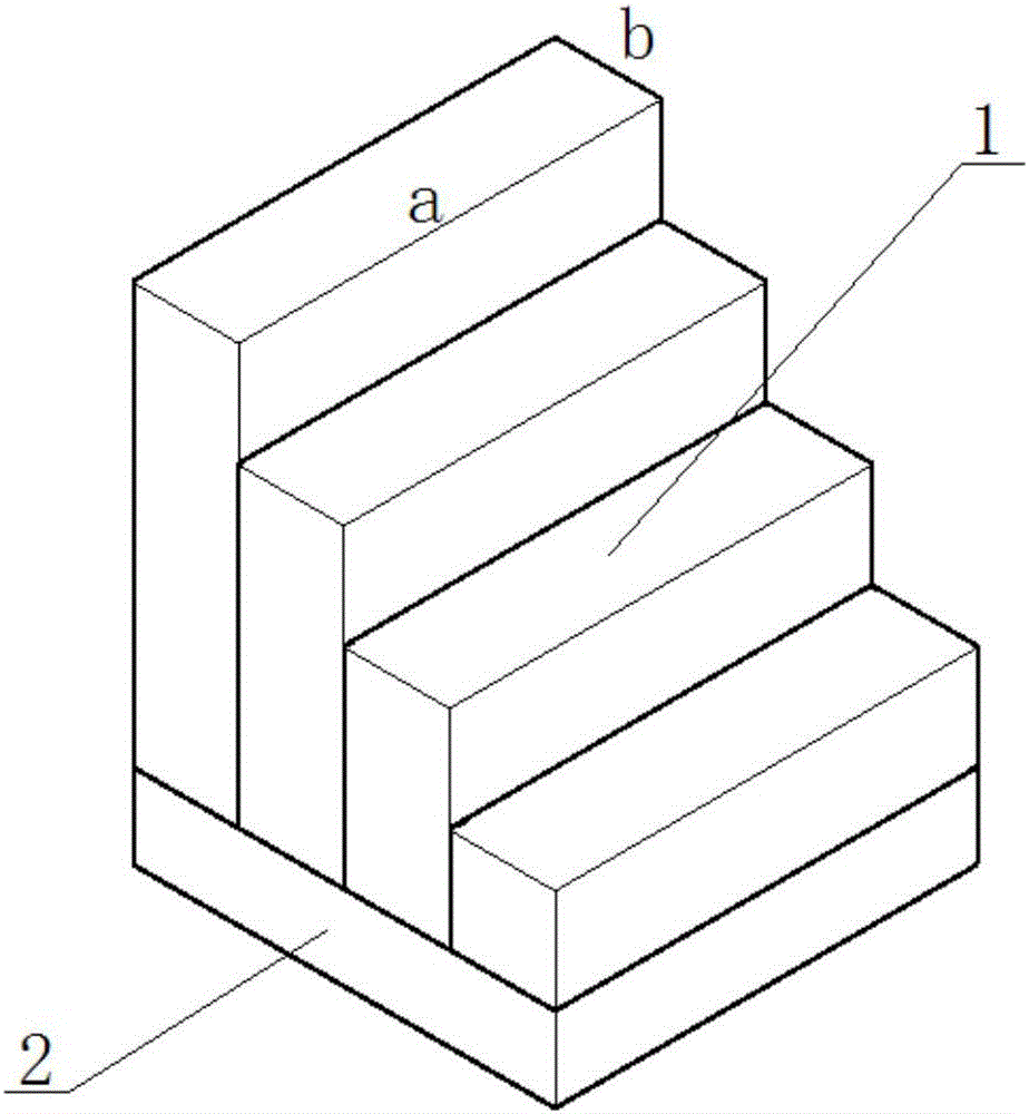
[0022] Such as image 3 , 4 As shown, a one-dimensional spatially stacked beam distributed phase retarder, wherein: the spatially stacked beam distributed phase retarder is a plurality of machined light-transmitting elements whose refractive index is not equal to the refractive index of air, Its structure is: machine-processed light-transmitting elements with a certain height difference and a refractive index not equal to the refractive index of air are bonded together.
[0023] For the machined light-transmitting element, glass is taken as an example. It is composed of glass layer 1 and glass base 2 with a certain height difference (see image 3 ), this embodiment has 4 layers. The length of each layer is a, the width is b, here a=4b, and then the one-dimensional machined light-transmitting elements are superimposed and assembled (see Figure 4 ), so as to achieve two-dimensional spatial distribution of phase modulation.
[0024] A speckle elimination method using a one-dimensional spatially stacked beam distributed phase retarder, the steps of which are: expand the laser beam emitted by the laser light source, pass through the glass layers with different height differences, and the beam is generated inside each glass layer Optical path difference, when the optical path difference is greater than or equal to the laser coherence length L C When the light beams passing through the glass layer produce a certain delay in time, the coherence of the laser light is destroyed, and the laser speckle is suppressed; the number, length and arrangement of the glass layer are set as needed (see image 3 , 4 ), where the layer width b is greater than or equal to A C Is the coherent area. The laser beam emitted by the laser light source is expanded through the glass layer, and a single coherent laser beam is divided into 64 incoherent independent light sources, which destroys the coherence of the laser spatially and reduces the speckle contrast.
[0025] It should be noted that the arrangement of heights can be from low to high (see image 3 , 4 ), it can go from high to low, or from low to high and then lower, and even can be arranged randomly. Requirements: the optical path difference of the light beam through the machined transparent element is greater than or equal to the coherent length L C , The area of ​​a single incoherent illumination source is greater than or equal to the coherent area A C.
[0026] The dimensions described in the present invention are functional divisions rather than specific geometric structures. The dimension of the present invention corresponds to the propagation direction of light and perpendicular to the propagation direction of light, and corresponds to time and space. Time is embodied in the coherence length, and the existence of the height difference makes the light phase retard in the light propagation direction; while the space is embodied in the cross section of the structure, which retards the light in the direction perpendicular to the light propagation direction. For example, for 4×4 units, the bottom area of ​​each unit must be greater than or equal to the coherence area. In a one-dimensional device, the layer width b is determined. When two one-dimensional assemblies are assembled, their overlapping bottom area is 2a× 8b, the area of ​​a single unit is b×b ​​(b×b ≥ coherence area).

PUM

no PUM

Description & Claims & Application Information

We can also present the details of the Description, Claims and Application information to help users get a comprehensive understanding of the technical details of the patent, such as background art, summary of invention, brief description of drawings, description of embodiments, and other original content. On the other hand, users can also determine the specific scope of protection of the technology through the list of claims; as well as understand the changes in the life cycle of the technology with the presentation of the patent timeline. Login to view more.

Similar technology patents

Classification and recommendation of technical efficacy words

  • Easy to assemble
  • Simple device structure

Mahjong machine

Owner:德兴市永达娱乐设备有限公司
Why Eureka
Try Eureka