Pressure applying mechanism of polishing pad activator for CMP equipment and operating method thereof

A polishing pad and activator technology, which is applied in metal processing equipment, grinding/polishing equipment, grinding machine tools, etc., can solve the problems of increasing the cost of the polishing process, unstable downforce supply, and affecting the wafer forming rate, etc., to achieve The effect of small loss, controllable pressure and low time cost

Active Publication Date: 2017-05-17
BEIJING SEMICORE PRECISION MICROELECTRONICS EQUIP CO LTD
View PDF8 Cites 4 Cited by
  • Summary
  • Abstract
  • Description
  • Claims
  • Application Information

AI Technical Summary

Problems solved by technology

[0005] The invention provides a polishing pad activator pressure-applying mechanism for CMP equipment and its operating method, which solves the problem of air bag wear and tear during frequent up and down movements when the air bag cavity is used to adjust the pressure on the polishing pad in the prior art. Large, short life, easy to deform, unstable position, resulting in unstable downforce supply, affecting the wafer yield, and greatly increasing the cost of the polishing process.

Method used


Image

  • Pressure applying mechanism of polishing pad activator for CMP equipment and operating method thereof
  • Pressure applying mechanism of polishing pad activator for CMP equipment and operating method thereof
  • Pressure applying mechanism of polishing pad activator for CMP equipment and operating method thereof

Examples


Embodiment Construction

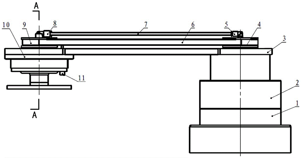
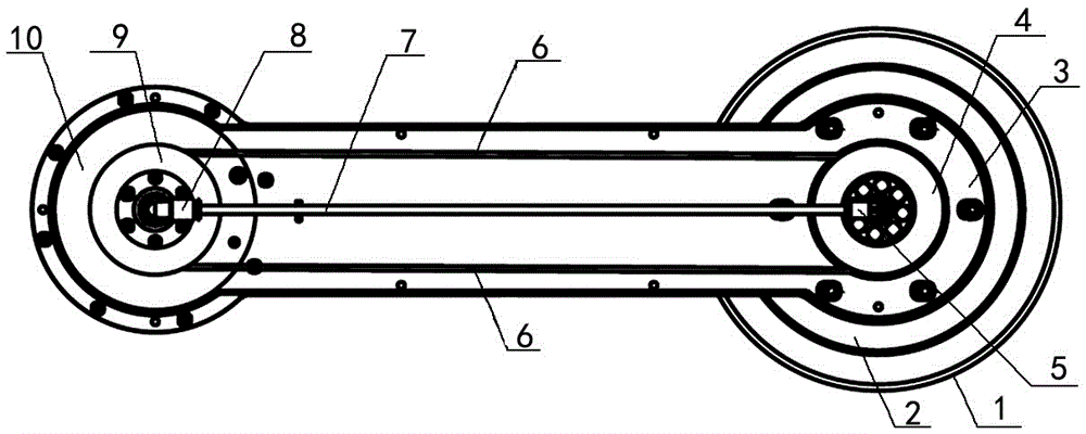
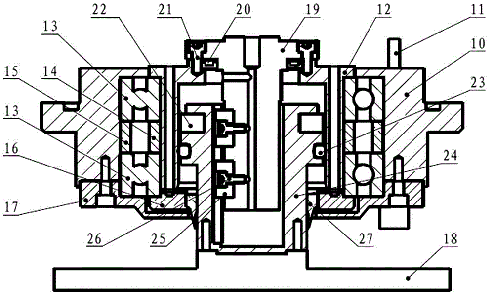
[0031] Hereinafter, embodiments of a polishing pad activator pressing mechanism for a CMP apparatus and an operating method thereof of the present invention will be described with reference to the accompanying drawings.

[0032] The examples described here are specific specific implementations of the present invention, and are used to illustrate the concept of the present invention. They are all explanatory and exemplary, and should not be construed as limiting the implementation of the present invention and the scope of the present invention. In addition to the embodiments described here, those skilled in the art can also adopt other obvious technical solutions based on the claims of the application and the contents disclosed in the description, and these technical solutions include adopting any obvious changes made to the embodiments described here. Replacement and modified technical solutions.

[0033] The accompanying drawings in this specification are schematic diagrams, ...


PUM


Abstract

The invention relates to a pressure applying mechanism of a polishing pad activator for CMP equipment. The mechanism comprises a bearing assembly, a power arm assembly, a transmission assembly and a gas path assembly; a bearing isolating sleeve is mounted between two ball bearing end surfaces in the bearing assembly in a sleeving manner; a sealed loss-preventing sleeve is arranged between the inner end cover of a bearing at the lower end surface of an air cylinder and a position shaft; a seal ring is arranged between a flange disc of a rotary shaft and a combining end surface of the upper end surface of the air cylinder for sealing; a guiding hub hole matched with a guiding key of the rotary shaft is formed in an inner cavity of the piston shaft, an O-shaped seal ring and an opening magnetic ring are embedded onto the external end surface, a grinding wheel disc which is horizontally arranged is fixedly connected to the lower end surface, and a pressure sensor is fixedly connected to a bearing pedestal. According to the mechanism provided by the invention, the rotary shaft, the air cylinder and the piston shaft are matched with the seal ring and the O-shaped seal ring to form a sealed cavity which replaces a conventional air bag cavity, so that the resources are saved, the cost is lowered, the loss is small, the service life is long, the reliability is good, the precision is high, pressure can be controllable, and the yield of wafers is improved.

Description

technical field [0001] The invention relates to a polishing pad pressing mechanism, in particular to a polishing pad activator pressing mechanism for CMP equipment and an operating method thereof. Background technique [0002] In the semiconductor integrated circuit manufacturing industry, the wafer needs multiple chemical vapor deposition to form a dielectric layer in the process of manufacturing devices in the front process, and each deposition will increase the surface fluctuation of the dielectric layer on the original basis; Multiple times of chemical and physical vapor deposition are required to form metal layers. When there are more than 3 layers, it is basically impossible to form effective photolithography. Therefore, it is necessary to planarize the surface finish of each layer. Traditional integrated circuit planarization methods include: heat flow method, spin-on-glass method, etch-back method, and electron surround resonance method. Only local planarization of ...

Claims


Application Information

Patent Timeline
Patent Type & Authority Applications(China)
IPC IPC(8): B24B53/017B24B53/12B24B37/34
CPCB24B37/34B24B53/017B24B53/12
Inventor 姜家宏李伟王铮熊朋
Owner BEIJING SEMICORE PRECISION MICROELECTRONICS EQUIP CO LTD
Why Eureka
Try Eureka