
Method and device for improving biomass compression moulding rate

A technology of compression molding and biomass, which is applied in the direction of material molding presses, presses, mold extrusion granulation, etc. It can solve the problems of high energy consumption, poor molding effect, and low production efficiency of biomass compression molding. Achieve the effect of improving the quality and effect of bonding molding, avoiding bad molding effect, and improving production efficiency

Active Publication Date: 2017-05-17
金湖禾一生物科技有限公司 +1
View PDF4 Cites 0 Cited by
  • Summary
  • Abstract
  • Description
  • Claims
  • Application Information

AI Technical Summary

Problems solved by technology

[0005] The purpose of the present invention is to solve the problems of high energy consumption, low production efficiency, poor molding effect, and prone to pressure loss and puffing in the existing biomass compression molding, especially for crop straws and rice husks with low lignin content In order to solve the problem that the biomass raw material is difficult to form, a method and device for improving the compression molding rate of biomass were invented

Method used


Image

  • Method and device for improving biomass compression moulding rate
  • Method and device for improving biomass compression moulding rate

Examples


Embodiment 1

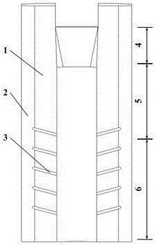
[0035] Such as figure 1 shown.

[0036] A method for improving biomass compression molding rate, comprising the following steps:

[0037] Firstly, an exhaust passage 2 is set between the molding die 1 and the body of the main molding machine. The main molding machine adopts a hot pressing molding process, and the molding temperature range is 100-200°C. The mouth is connected, and the biomass raw materials (such as wheat straw, rice straw, corn straw, rice husk, forage grass, etc.) at the feed port are treated with the heat of the exhaust channel 2. The moisture content of the biomass raw material ranges from 10% to 25%. ) for heating;

[0038] Secondly, vent holes 2 are arranged on the cavity wall of the shape-preserving section 6 of the molding die 1, the angle between the center line of the vent hole and the center line of the die hole is less than 90°, preferably 45°-90°, and the aperture is 2 to 5mm, the angles of each exhaust hole 2 can be equal or not, and the hole di...

Embodiment 2

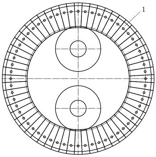
[0042] A device for improving the compression molding rate of biomass, which includes a molding die 1, and the installation form of the molding die 1 is as follows figure 2 As shown, a plurality of exhaust holes 3 are arranged on the cavity wall of the shape-retaining section 6 of the molding horizontal 1, and the exhaust holes 3 communicate with the exhaust passage 2, and the exhaust passage 2 is located outside the molding die 1 and Forming between the host body. The included angle between the centerline of the vent hole 3 and the centerline of the die hole is 45°-90°, and the diameter of the hole is 2-5mm. The included angles between the central line of the vent hole 3 and the central line of the die hole are the same or different, and the apertures are the same or different.

[0043] According to the different processes of biomass compression molding, the die hole of the forming mold can be divided into three parts: pre-compressing section 4, forming section 5 and shape-...


PUM

PropertyMeasurementUnit
Angleaaaaaaaaaa
Apertureaaaaaaaaaa

Abstract

The invention relates to the technical fields of agricultural equipment and biomass energy, in particular to a method and a device for improving a biomass compression moulding rate. The device comprises a biomass compression moulding main engine device and a moulding mould provided with vent holes, wherein a vent passage is arranged between the moulding mould with the vent holes and the engine body on which the moulding mould is arranged, so that vent smoothness is ensured. The method and the device have the beneficial effects that production efficiency is high; energy consumption is low; a moulding effect is good; and the method and the device have good adaptability to biomass materials which are difficult to compress and mould, and can be widely applied to the technical field of fodder or biomass moulded fuel processing.

Description

technical field [0001] The invention relates to a biomass raw material processing technology, in particular to a compression molding technology for straw feed or biomass molding fuel raw materials in biomass, in particular to a method and device for increasing the compression molding rate of biomass. Background technique [0002] With the increase of the world's population and the improvement of living standards, the human demand for energy is increasing day by day. Energy shortage and environmental pollution caused by the use of fossil fuels are the greatest challenges facing human society. The development and utilization of renewable energy is the key to solving this problem. Biomass energy, as a renewable energy source, has unique advantages and huge potential for development and utilization. my country produces a large amount of crop straw and forestry waste every year, except for a small part that is recycled, most of which are discarded in the field or buried or dire...

Claims


Application Information

Patent Timeline
IPC IPC(8): B30B11/22B30B15/00B01J2/22
CPCB01J2/22B30B11/22B30B11/221B30B15/00B30B15/0017
Inventor 高翔王子玉高峰郭卫忠姚勇刘军
Owner 金湖禾一生物科技有限公司
Learn More